It is important to know it's equipments limits. So testing the magnetic tracker is good to see the accuracy of this tool in the environment it will be used.
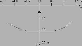
A post mounted on a plate was used. In a height of 1.58 meters a sensor was mounted. The Flock of Birds transmitter is mounted in 2.19 m height. This measurement unit was moved along the Y-axis from -1.3 m to 1.3 m. The steps the unit was moved is 10 cm. At every step 5 measurements where done and the mean value taken to avoid wrong results influenced by jitter. The result can be seen in Figure 4.1. It can be easily seen, that the tracker works with high accuracy while the distance to the transmitter is not more than 0.5 - 0.6 meters. If distance to the transmitter is more than about 1.0 m the distortion is significant and getting worse and worse with further increasing distance. The results show, that the field gets more disturbed on the + side than on the - side. One possible reason is the near distance to the wall and a column with lots of iron inside.
One effect not shown is the jitter becoming worse with increasing distance. Sometimes values coming from the tracker are completely wrong. This is not easy to measure, but can be seen best, when watching a 3D model showing the position and orientation of a sensor. The model is suddenly jumping to another place and is back in the next moment.
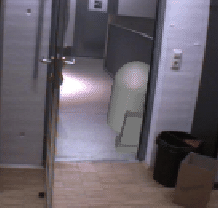
A small application was taken to implement a program with pure Studierstube (that means without windowing, distribution, and other complex techniques). The application simulates a light-saber known by the movie Starwars, and a robot (let's call him R2D2) should walk on the corridor outside. R2D2 should be seen only if he is in the door.
The saber is a simple model consisting two cylinders. One for the sword, one for the hold. Geometry and material is set with OpenInventor. The position of the saber is taken from a Tracker-engine. Studierstube provides the OpenInventor-engine[12]. The engine holds position and orientation of every sensor. The position and orientation of the sensor mounted on the Pen is taken. So the Pen feels like the hold, and the user sees the light-saber instead.
The program itself is very simple. There are only some lines of code, that start Studierstube and load one OpenInventor file. The rest of the work is done in the file loaded. There the saber is made, and connected to the trackerengines output that corresponds to the pen. The robot is made, and a shuttle transformnode lets R2D2 walk. The interaction of R2D2 and the door is made with two cubes that are at the position of the walls. The cubes are drawn black and therefore can't be seen in the display. R2D2 is automaticly drawn correct by the rendering engine.
A second application is jumping ball. A ball with 5cm radius starts falling
from 2 m down to the floor. Gravity is taken into account, and if the ball touches
the floor or any furniture the ball rebounces. The ball also has some speed
for ![]() and
and ![]() direction.
direction.
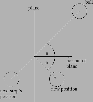
The program has an object ``ball''. This object holds the direction, position, gravity, take off power and routines for calculating the next position, the effect of gravity and reflection at a plane. A general routine calculates if the ball will touch any furniture, the floor, or any wall. An exact model of the office room is needed with all its furniture, monitors and computer to make this possible. The model is stored in an OpenInventor file as an indexed face-set.
To calculate if there is a reflection the ball is reduced to a point. This not correct, but is sufficiently accurate for this demonstration application. The point of intersection of the line defined by the balls position and direction with every plane in the model is calculated. If the intersection point is nearer than the distance the ball will make in the next step, then an reflection could happen. To check this it must be seen if the point is inside the triangle or outside. Therefore for all three triangle edges it is checked if the point is inside or outside.
If a reflection occurred then once again it is checked if another reflection happens. But in the second control, the point of intersection, and the rest of the distance is taken. The second control must be done, because otherwise it could happen that the ball leaves the room in the edges.
Gravity ,take off power and the time-slots used for calculating the balls next position can be changed easily. It would be an option to change these values by sliders on the panel. With this method the user could change the speed and the balls behavior. Even a racket controlled by the pen could be implemented to make a virtual office squash.