Realistic Sailing a Virtual Ocean
Vladimir Stepan
stepanv@cslab.felk.cvut.cz
Department of Computer Science and Engineering
Czech Technical University
Prague/ Czech Republic
Content
Abstract
This paper describes a part of the Yacht Captain Training System project, particularly the part that includes ships and scenes modelling. It is divided into two parts. The first deals with problems of practical usage of VRML standard for basic 3D modelling, while the second inquires the possibilities to make virtual sailing more realistic.
Keywords: VRML, modelling, yachting, ocean, waves
1.Introduction
The goal of this project is to prepare realistic scenes for Yacht Captain Training system with realistic scenes. That means a great deal of modelling. The first is the modelling the ships and other objects, then putting those together in a scene and finally making a scene look real. The realism of the scene is to be achieved while maintaining the simplicity and good frame-rate.
The modelling of the objects and scenes is relatively part, though complicated a little by the demands for simplicity. The modelling isthe topic of the first part of this paper - the chapter 2. It includes the specifications of several interesting aspects of a task, brief description of a model-ship structure and also some tips, tricks and experiences.
The subtasks, that could not be solved purely by the means provided by VRML are the subject of the second part. Chapter 3 describes the ship night signalling system which had to be visualized precisely for its importance for captain training. The most interesting is "the virtual ocean" and "the drunken sailor-avatar", the simulation of waves - motion of water and motion of floating objects, including the viewpoint. This is described in chapter 4.
2.The Modelling
The following paragraphs introduce several issues concerning the modelling. Examples taken from the "Realistic Sailing" project are being discussed too.
2.1Efficiency problem
One of the chief requirements in virtual reality modelling in general is the balance between the authenticity and the simplicity (the rendering speed) of the model.
The VRML offers an LOD (Level Of Detail) node which allows to limit the number of points and faces in a scene. This construction though, does not solve the problem on itself. It is necessary to keep those amounts as low as possible from the very beginning by constructing the shapes carefully and using other tricks.
2.2Textual or visual editing
There are basicaly two different approaches to modelling: to visually edit the world (e.g. 3D Studio) or to edit the code (e.g. by Notepad). Our oppinion is that the second is better although the idea of creating a VRML scene with just a Notepad is a little scary. Fortunatelly we are not left alone with a Notepad. Not being paid for advertising we recommend to use ParallelGraphics VRML Pad code editor. All models for the Yacht Captain Training System have been modelled using this powerfull and valuable programmer's tool.
The code editing is the way to get the best knowledge of all the points and faces used in a scene, that we possibly can. Besides that, writing the code enables us not to get lost in it when we are forced to actually edit it.
2.3Choice of a shape geometry
There are more ways in VRML how to create a specific shape.
Primitives:
It is encouraged to use primitives when possible (Box, Sphere, Cone and Cylinder). Combining them with non-uniform scale transformation can express a lot.
Extrusion:
When using an Extrusion there is a danger of generating too many points. It is useful to keep in mind that their number will be number of CrossSection points times number of Spine points.
The choice of a zero point of a CrossSection has a great significance, combined with different scale for each Spine point.
it can be easily used for generating various trapezoidal shapes.
IndexedFaceSet:
IndexedFaceSet seems to be the best choice of shape's geometry as far as the control over points and faces is concerned. Anyway, we recommend a help of a paper and a pencil while writing its code.
During modelling of the ships for the system we have come to the following common principles concerning efficient description of a ship:
Ship hull - an IndexedFaceSet of 22 points. Each ship has the same hull part, only with different coordinates of points.
Masts, yards and all kinds of poles - Extrusions with a eight-point CrossSection and two-point Spine. Due to an effect of the mast narrowing from the base to the top it is not recommended to use the Cylinder primitive.
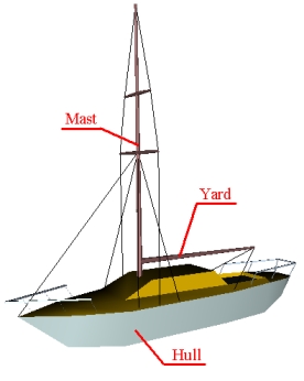
Figure 1: Explanation of special vocabulary
2.4LOD
Our LOD variants were derived from the most detailed model. That we have created first starting with a sketch on the paper. In a process of creating such a sketch we mark the most significant points to get the proportion. Then we continually add more points and the shape gets more detailed. For creating the lower levels of detail we used the opposite process. We either skipped whole parts of a tree or just the points from the nodes that were to remain.
The Extrusion shapes can be simplified easily by skipping some points from the CrossSection. On the other hand the IndexedFaceSet simplification was set back a little by the necessity to redefine polygonal faces after removing points.
IndexedFaceSets or Extrusions that resemble a box at certain level of abstraction should be replaced with a Box primitive in lower levels of detail.
The decision what part to remove depends strongly on particular model, its shapes, colors and contrasts of colors.
2.5Other tips
Lines:
The problem with using an IndexedLineSet is that the line defined in this way is always of the same thickness, no matter how small gets the whole model when in the distance. It is good to use it only in the most detailed LOD variant.
SizeOf Faces:
The decreasing of amount of points and faces is not always the best way. Sometimes it is better to use several smaller faces instead of a
large one. The face has just one color.
The problem appears if one end of a large plane is lit in a different way then the other, or is in a fog while the other is not. These are the situations when the continual change of color should occur. The color of a large face will be average, therefore it is better to use
several smaller ones to get the effect.
3.The Night Signalling System
At night it's necessary to provide the vessel with the light signalling system. It is defined system which enables to unambigously specify the position of a ship towards the observer, the type and the activity of the ship.
The signal system consists of three position lights - red (left), green (right) and white (back), eventually white pole-lights (visible in certain angle) of a vessel with an engine drive and additional special lights that inform of a type, activity or a situation of a vessel. These are ussually the circular lights, which means that they are visible from any direction.
3.2The exclusive visibility of position-lights
The three position-lights are to unambigously define the position of a ship. Except for the case when the ship goes towards the observer, only one of the three lights may be visible. This rule became a source of some problems during the modelling of the lighting system. In the real world it is not easy to hold on to this rule, but the computer system should follow the rules.
If there was a model of a lamp covered on the sides, where the light wasn't supposed to be seen, the problem appeared that, as a result of rounding the values when computing, either two lights or none appeared in the areas close to the critical angles.
Figure 2: Position-lights system
3.3The solution
This problem was solved by using a simple script in a scene. This script checks the position and an angle of the ship refered to an avatar and sends an actual value to a switch of a lights models. Thus there are four (front, back, right, left) models of lights for each vessel. Switching among them solves the problem of exclusive visibility of the position-lights.
4.Virtual Ocean
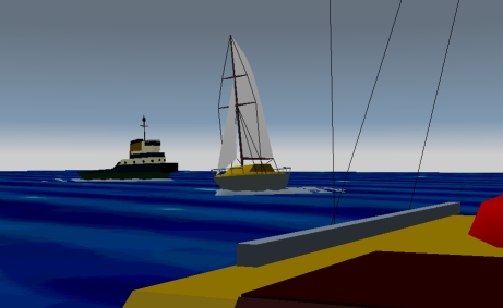
After creating model ships we can make scenes with ships shifting through space. There is no actual sea, just the illusion of sea, sky and horizont, created by background. Such scenes can serve undoubtedly better than present form of simple-image-on-the-paper tests. It is not much of a sailing experience though.
To create the effect of unceasing turmoil of real ocean we need to add motion to a scene. Creating this illusion consists of two parts:
4.1Motion of ships
The rocking motion of floating objects is generated by a script. Its EventOut atribute is being sent to one of the rotation transformation in the ship's tree.
The choice where in the tree to put this rotation's node s quite significant. Since the orientation computing uses the direction of the waves, it is important to perform this transformation after the ship's heading direction is resolved.
The script depends on several influencing factors which are given to it as arguments. These are:
The idea of the inclination computing script is:
Closer explanation:
A TimeSensor sends startTime and time events. These are used to find a relative time. For farther computing it is good to divide the
result by number (n) greater then 1 - it affect the frequency of the "waves".
A = (time - startTime) / n
The next computing step is:
X = factor*function(A)
where
function(A) = 0.5*(sin(4*A)+sin(2*A+0.5))
factor = f (size, height) = height / (m*size)
Function used as function(A)does not necessarily have to be the one quoted above but it needs to generate values from the interval <-1;1> and its course should resemble the waves.
The factor expresses the influence of a waves' height and the ship's size and their relationship
At the end we gain the inclination angle:
Angle = asin(X)
Now the meaning of the factor is clearly visible. We can not use the angles greater than 45 deg. (or lower than -45 deg.), our experience is that it would not look realistic. Therefore:
This script does not describe the real motion of a vessel on the sea. That is a much more complicated problem that would include also the changes of rotation axis and other computing. But for the purposes of the Yacht Captain Training System it serves well enough. The illusion of rocking motion is quite convincing, especially if the function(A)is different for each floating object, including avatar. It was a pretty succesfull attempt to turn avatar into a drunken sailor.
4.2The Waves
The ship's motion alone is not enough. With the sea expressed just by the background color the realism of the scene gets perhaps even worse when the ships and the viewpoint start to sway. There has to be also the image of the water surface in the scene.
We have already mentioned that one of the ways to create the illusion of water is to specify the color in the Background node. This was uses in previous stages of the Yacht Captain Training System, but does not suit at all to the new demands, that started the "Realistic Sailing" project.
Another way is to represent the water as an IndexedFaceSet connected to a CoordinateInterpolator that changes the ycoordinate value of particular points.
The distance between particular points shouldn't be too great in order to get steeper waves as well as flat ones without getting them too high. The moving part of surface does not need to reach very far from the avatar but because of the demand for the distance between the points this solution would still generate large amount of points.
The visibility of the waves effect is not good enough compared to the costs measured by the number of generated points.
Or we can represent the surface as a set of larger tiles - IndexedFaceSets around the avatar (not just one large tile - see 2.5) with a simple texture
on it. Again this set of tiles can be relatively small compared to the size of the scene as a whole.
The texture should be animated for better realism. As a side-effect of avatar's rocking even the static image texture appears to be moving. This effect would not occur if the viewpoint was higher above the surface. But since the avatar never leaves its post aboard the small yacht. low above the sea-level the illusion of moving texture occurs at short distance.
This solution appears to be the best. Although the scene does not include other textures, a well designed water texture does not disturbed the consistency (but these are the artistic aspects of the project and we will not discuss them here).
The only obvious set-back of a texture solution is the flatness of surface which is clearly shown around the flanks of a ship or other floating object.
Figure 3: A sample of water textures (calm, stormy and night sea)
4.3A wake behind the ship
Modelling of a wake behind the ship is a task similar to modelling the waves. Though closely connected to a problem of waves we consider it a separate task. We used a representation of IndexedFaceSet combined with CoordinateInterpolator, and thus we also removed the setback of a water surface texture mentioned above. The shapes of the "wake" around the ship's flanks hide the flatness of surrounding water.
It is the only part of the project that has not been created in an environment of VRML Pad. The .wrl file that describes the wake has been generated by the specific program written for this purpose in C language. The program generates a square network of points. The y coordinates of these points are computed to create the effect of water stirred by a ship. Whole structure is then moved a little bellow the water-level so that only the tops of the waves are visible.
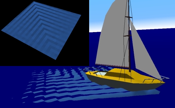
Figure 4: The structure of the wake and final effect.
The wake modelled this way adds a lot to the realism of the scene, but also takes a lot from the frame-rate. The side of the square should be at least 15 points (18 or 20 looks much better though), that means 225 to 400 points for each ship. The partial though not complete solution of this problem is LOD. The compromising between the realism and rendering speed is the most obvious in this part of project.
5.Conclusions
On one practical example we introduced several of the aspects and problems of using the VRML standard for 3D modelling. Also we sugested a few of the possible solutions of these problems. The result of this research is a set of models and scenes for the Yacht Captain Training System. The scenes do have a significant level of abstraction while still maintaining a considerable realism.
6.Future work
This project was the work of one person during the one semester. The only farther work within the boundaries of the "Realistic Sailing" project will be
Also the research in modelling clouds and other meteorological conditions has started.
7.References
[1] Zara J. : VRLM 97 Laskavy pruvodce virtualnimi svety, Computer Press, 1999 (in Czech)
[2] Haskovec J. : Rukovet namorniho jachtare – sesit 1 a 2, Czech Offshore Yachting Association, 1999