Modeling and Rendering of Metallic Patinas
The third and last approach that is presented in this work concentrates on weathering
effects, especially on patinas on copper and copper alloys.
In order to study the development of metallic patinas, Dorsey and Hanrahan chose copper
as representative metal. The patinas of copper and copper alloys are classical examples of
layered structures. When viewed in cross section multiple layers are distinctly visible to
the eye (see Image 12).
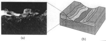
Image 12. Copper surface, showing the layers
Clean copper surfaces exposed to the atmosphere quickly form a thin layer of dull
brown tarnish that gradually changes with time to a reddish brown color, which is
indicative to copper oxide, or mineral cuprite. Once this layer is in place subsequent
layers grow much more slowly. The primary chemically constituents of the patina on copper
alloys include copper oxides, sulphides, and anorganic and organic copper salts.
The copper salts, consisting mostly of sulphates, chlorades, and nitrates, come in a wide
variety of colors. Copper sulphate causes the characteristic green color of aged copper.
The composition of copper patinas varies in the environments and average lengths of time for the development (see Image 13).
The left column represents four stages in patina growth in marine environment. The two columns on the right side represent stages
in patina growth on land. Whereas the middle column stands for rural and the right columns for urban environment.
It’s easily to see that the patina of different compositions is produced in each environment.
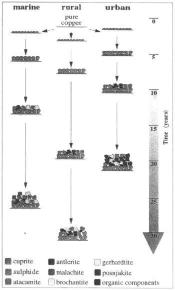
Image 13. A shematic diagram of processes involved in the growth of copper patinas in
marine, rural, and urban atmospheres.
Modeling
As described above, the development of a metallic patina is a process that proceeds in a system of layers.
Therefore a representation of the structure of a layered material and a set of operators that can be applied to
this representation is needed. By writing a script in terms of these operators, the weathering of the material
as a function of time may be simulated.
As a matter for simplification, each layer consist of a homogeneous material. Each individual layer also has a
thickness that may vary as a function of position. Each material’s surface has the standard set of surface
shading parameters, such as diffuse and specular colors and shininess. Light is reflected from the surface
depending of the given parameters. This surface reflection gives the layers a glossy appearance. Light is also
reflected and transmitted through the interior depending on the absorption and scattering properties of the
material. This fact, that light is also transmitted through a stack of layers, causes the colors to be mixed.
Underlying materials stay partially visible.
Hanrahan ad Dorsey introduce a number of operators to simulate the effects of patina growth.
- coat
This operator adds a new layer of material to the surface. A maximum thickness may be applied.
- erode
The erode operator removes material from a layered surface. The depth of the erosion may be controlled by a
thickness map. Material can be cut into and underlying layers may be exposed.
- fill
The fill operator deposits material up to a given absolute height above the base material. This represents a
simple way to simulate the deposition of material in cracks and crevices.
- polish
The polish operator removes material until a given absolute height above the base material is reached.
The result is a smoothing effect. The accessibility of each area can be used to control the amount of polishing.
- offset
The offset operator applies a material to a surface by first applying a thick coat and then removing the
part accessible to a sphere of a given radius. The offset surface is computed using techniques described by
Miller[3].
The given operators can be used to model a multi-layered patina. But the resulting layers will be completely
uniform and devoid of the variations that any natural process generates.
Therefore some physical plausible methods to modulate these operators across the surface are needed.
Hanrahan and Dorsey provide following models.
- Steady thickening (ST)
This model causes the thickness of the layer to increase with time, resulting in a very simple uniform pattern.
This effect is achieved by sampling a surface evenly with a small number of points. Each of this points gets its
initial thickness assigned. The thickness at intermediate points is interpolated. The user-given growth rate
increases the thickness at each sample point. To keep the appearance natural, a small amount of noise is added.
- Random deposition (RD)
From a randomly chosen position over the surface, a particle falls vertically until it reaches the top of the
surface under it. The height at the chosen position is increased by one.
This method can be varied resulting into random deposition with surface relaxation. The deposited particle is
allowed to diffuse along the surface up to a finite distance, settling when it finds the position with the lowest height
(See image 14 (a)).
- Ballistic depostion (BD)
Again a particle is released from a randomly chose position above a surface and falls vertically until it
reaches the surface, whereupon it sticks. But this method enables the particle to stick to the edge of neighboring points,
resulting in lateral growth (See image 14 (b)).
- Directed percolation depinning (DPD)
This method starts with a collection of initial patches on a surface. An interface develops that grows in all
directions in two dimensions and increases in thickness. A percentage of cells is marked as blocked and others
are marked as unblocked. Over time patches are much more likely to advance onto an unblocked cell than a
blocked cell. Unblocked cells can be interpreted as implying moisture on the surface and thus stimulating growth.
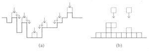
Image 14. (a) Random deposiotion with surface relaxation. (b) Ballistic deposition.
Scripts
Using the introduced scripting language, the described operators and modulations can be applied to a surface.
new copper;

coat tarnish_1 0.35 texture(BD_linear_1_20);

coat cuprite_2 1.2 texture(DPD_linear_5_40);

coat marine_patina_3 3.0 texture(BD_linear_10_20);

coat marine_patina_4 1.8 texture(DPD_linear_20_40);

erode 0.5 texture(BD_linear_5_20);

render maps;
This simple script simulates the growth of patina in marine environment.
The models are identified with the
algorithm name, growth rate, step number, and number of steps. Names such as marine_patina_3 signify mixtures
of substances outlined in image and are treated as materials with the various operators. BD and DPD models are
used to vary the thickness of the layers as a function of time. The BD model yields to spotty patterns that are
characteristic for marine environments. The DPD model provides a patchy but more uniform coating of patina in the latter stages.
In the last step a small portion of the top layer is eroded away.
Results
Image 15 shows the development of the patina on a small statuette of Buddha.
Table and wall are rendered using
conventional texturing techniques, and the statuette is rendered using the techniques described above.
A three layered surface has been modeled: base copper, a tarnished layer, and green patina.
The thickness of the tarnish layer was computed using two functions. The first models tarnishing due to
atmospheric processes. The second parameter shows the decrease in tarnish thickness due to polishing the statuette.
Unlike the first parameter, this one does vary spatially as determined by the accessibility map. This map has been
computed by using the methods by Miller described in Accessibility Shading. Thus tarnish appears in cracks an crevice,
and shiny copper appears in exposed areas.
The green patina consist of a steadily thickening layer and random patches. The layer depends on the local wetness of the surface.
This wetness has been precomputed using an exposure map, that gives the average irradiance due to the sun and sky received by that
part of the surface. The wetness along the base of the statue where water is likely to accumulate is increased steadily by a simple function.
The random patches are controlled by a random fractal surface growth process.
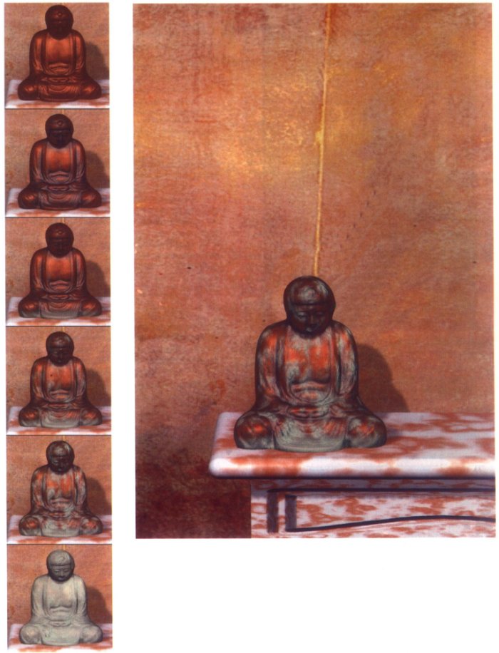
Image 15. 'A sense of time'. The aging of a statuette.
Go to Summary and References.