
Vision-based camera matching using markers
Gábor Blaskó
blasko@indigo2.hszk.bme.hu
Computer Graphics Group
Department of Control Engineering and Information Technology
Technical University of Budapest
Budapest / Hungary
Videos: Video1, Video2, Video3.
Abstract
This paper presents a method for calculating the unknown camera parameters of a real world camera based on markers placed at the scene. Camera matching, real and virtual world viewpoint synchronisation, and image generation form the basis of virtual studio and augmented reality applications. A non real-time version of the camera matching system was implemented and integrated into a professional 3D modelling program, enabling the enhancement of real world images with computer graphics.
Keywords:
camera matching, virtual studio, augmented reality, computer graphicsIn the world of television and film the use of computer graphics offers a lot of new possibilities. Non-existent environments, objects and even living creatures can be created with computer graphics programs. However, the integration of the real and the computer generated worlds poses the problem of viewpoint synchronisation. In the process of layering together the real-world and the computer generated images, which is called compositing, the viewpoints of the two “cameras” should have the same parameters, otherwise the perspective distortion and positioning of the images would make the layering process obvious and the final image would be unconvincing.
Besides those possibilities which can be achieved in film post-production, a real-time implementation of camera matching can be used in virtual studio and augmented reality applications.

Figure 1. Chroma-key compositing (background, foreground, key image / alpha mask, final composited image)

Figure 2. Augmented reality example (original image, 3D virtual object, augmented image)
For both applications a method called vision-based viewpoint matching offers a solution. It involves calculating the camera parameters based on the image(s) of the same camera. Three types of vision-based systems exist for calculating camera parameters, which use:
The method presented in the following uses the first approach. This work is inspired by, but not based upon these systems. In order to serve as the foundation of a future real-time system, either virtual studio or augmented reality, the algorithms used were derived from the basics, thereby allowing optimisations and fast implementation.
First, possible applications for augmented reality shall be discussed, with examples. In the following sections our experimental system’s outline shall be presented followed by a description of the algorithms and calculations used. Later the implementation of the system is discussed, mentioning further enhancements presently under development. Finally the working system’s performance will be evaluated.
Presently augmented reality technology is still in it's infancy. Several experimental systems exist, which were developed for different uses. Major directions of development are briefly presented in the following sections.
In the field of medical imaging three dimensional data is collected about the inside of the patient with the help of CT (Computed Tomography), MRI (Magnetic Resonance Imaging), and ultrasound imaging. This three dimension volumetric data is presently seen by the surgical doctor separately from his view of the patient. AR technology, could mix these two worlds, thereby giving the doctor ”X-ray vision” of the inside of the patient. With the use of a head-mounted display the surgeon could examine the patient with his naked eye and the overlayed images from the CT or MRI, thereby giving doctors access to both types of data simultanously. AR technology could enable high level surgical training and the widespread use of minimally-invasive surgery, where the doctor makes small incisions on the patient, or no incision at all.
Soldiers on the ground and in the air seldom have the time to collect information during combat. They have to make decisions in seconds based on the information they have in their memory, and what they see around them. They do not have the time to take out a map of the battle ground, figure out where they are, like a tourist in a foreign city. Thanks to GPS technology the soldier can determine his position on the globe. Then the AR system allows him not only to see his position numerically, but with the aid of a terrain database and satellite images to quickly access more information visually. He could look around and see the height of the mountains, the directions toward the camp, or the enemy tank behind the hill or a building from an “eye in the sky”.
For a helicopter pilot, AR could give basic navigation and flight information, but in the case of combat he could aim his missiles and guns, just by looking at the target.
The assembly and maintenance of complex machinery and equipment often require skill and practice. Instructional manuals include a lot of text and pictures, but even so professional practical training requires a lot of time and the aid of a trainer. It would be easier to produce the instructional material in AR form. The trainee could see superimposed images and annotations on the actual equipment, while listening to step by step instructions. Viewing animations of the tasks that need to be performed on the equipment make learning easier, than reading books and trying to figure out what the flat picture tries to show.
In the area of visualization the uses for AR are almost ”unlimited”, once all the technical obstacles are conquered. Architects can visualize new buildings on an empty site, everyday people can be given navigational information in an easily understandable way, directors can actually see the virtual dinosaurs during filming, industrial designers can see their designs in real life environments and change them, etc. In all areas where decisions have to be made quickly, where the needed information is more easily understandable in visual form, or simply the enhancement of the real world is needed Augmented Reality will provide a new solution.
The use of the camera-matching program can be divided into the following steps: image acquisition, marker identification, camera parameter calculation, rendering and compositing.
In a vision-based camera matching the primary input for the system is a picture taken of a real scene. This picture can be a single image taken by a regular camera and then scanned into the computer, a digital photograph, or a sequence of images digitized from a video recording. When recording an image, measurements need to be taken of 4 points, which can be later recognized on the picture. If the 4 points are simply recognizable features, like corners of objects, their 2D image coordinates can later be manually specified or high level feature tracking algorithms can be used to identify and track points, used as markers. If the 4 points are clearly marked in the real world, by color coded markers or fiducials, their 2D coordinates can be automatically recognized and tracked throughout the image sequence. Automatic marker recognition enables sub-pixel precision specification of the 2D coordinates of the markers.
The marker identification method used in this system applies small markers (paper squares) which can be easily identified, since their color greatly differs from their surroundings. As input information, the RGB color of the marker is set with a tolerance range setting. The pixels of colors within the given color range are identified as a part of the marker.
Since the markers are small in size and do not move too quickly in the case of an image sequence, only small rectangular regions around a given marker center point are sequentially searched within the picture. At the end of this search, the center of gravity of the markers are calculated. This information is passed on for further processing. In the new image of an image sequence, the center of the new search area can be the same as the center of gravity the same marker of the previous image. I shall refer to the four 2D coordinate pairs of the markers in the images as: 
In order to make the connection between the image of the real world and the three-dimensional space of the virtual world, a link is needed. The markers serve as the link. This is the point when we need the real-world measurement information collected during the recording of the picture. The real and virtual world coordinate systems can be connected relatively, therefore only the relative distances of the markers are needed. For example, one of the marker points can be defined as [0,0,0], i.e. coordinate system origin of the virtual world. If the markers are placed on a plane, like the corners of a square, only one measurement needs to be taken of the length of the square’s side, minimising the amount of information which needs to be collected on-site. Note that most of the camera-matching systems do not allow the points to be coplanar, making it necessary to place the markers in non-coplanar positions. This causes difficulties, since taking three-dimensional measurements is often difficult, especially outdoors. This real-world 3D information of the 4 markers will be called:
The other information needed, since the final calculation shall be performed with iterations, is a preliminary estimate of the camera parameters. The needed precision of this estimate depends on the scale of the subjects in the picture (cm-meters) and the relative distance of the markers in the 2D image. This estimate of the camera parameters is marked by:
 referring to the relative position [Xo,Yo,Yo] of the camera to the markers in the defined virtual world, the Roll, Pitch, Yaw rotational angles
  and the focal length of the lens: [c].
Camera parameters are usually separated into internal and external parameters. In most applications only the external parameters (position, orientation) of a camera are calculated, and updated, while the internal parameters (focal length, coordinates of the projection of the optical center, pixel length, width) are precalibrated and are kept constant during use. Since this is an experimental system, we supposed that the pixels were squares, the projection of the optical center was precise [0,0], and did not take into account other lens distortions. These presumptions naturally cause minor computational errors, but extremely high precision was not required in this system. However the possibility of varying the focal length during use was allowed. In a possible virtual studio system the freedom to change the focal length with a zoom lens should be provided.
With the use of the 2D and 3D coordinate information about the markers, and with the estimated camera parameters as inputs, the precise camera parameters can be calculated. Our viewpoints of the real world and the virtual world become synchronized, making it possible to integrate the two worlds. A computer generated image from the virtual camera positioned in the virtual world of virtual objects has the same perspective projection as that of the real world. The two images can be layered on top of each other with the use of either the alpha map generated for the rendered image, or using one of the colors of the real world’s picture to produce an alpha map with chroma-keying.
Depending on the use of the camera-matching system, either the computer generated or the real world image can be the foreground or the background image during compositing. In the case of an image sequence, if the camera parameters are constantly synchronised and updated from frame to frame, the image layering can produce the effect of reality enhancement, i. e. augmentation.
Using a perspective projection model [13], if a point P(X,Y,Z) is centrally projected onto a plane, being at distance c from the center point, the image of the point is  . If the direction of this projection can be described by an R rotational matrix, the connection between the image coordinates and the world coordinates of a point can be written into two equations (Equation 1.)[4].
Where rik are parameters of the R rotational matrix. (Equation 2.) The other variables can be seen on (Figure 3).
In (Equation 1.)  are know for each marker. The parameters c,X0,Y0,Y0 and rik are unknown and need to be calculated.
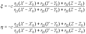
Equation 1. Relation of image and world coordinates

Equation 2. R rotational matrix
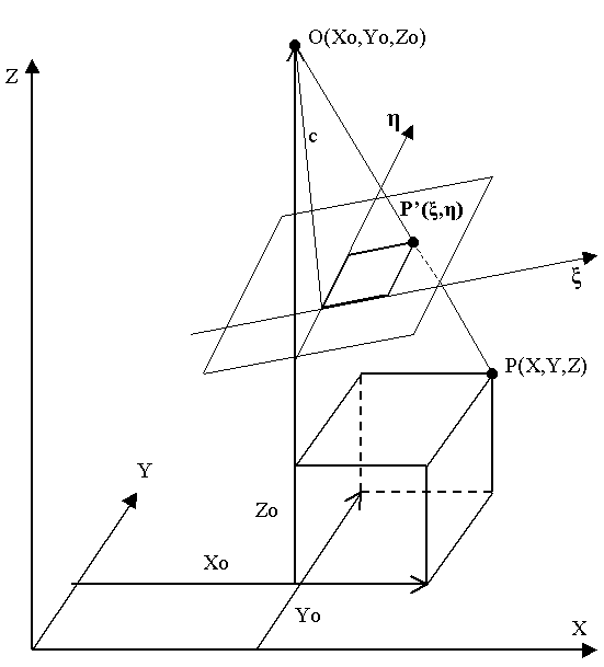
Figure 3: The connection of image and world coordinates.
The nonlinear system of equations can be solved by using the Newton-Raphson method as described in [5]. It is one of the fastest multidimensional root finding methods, with quadratic convergence if the initial approximation is sufficiently close to the real root. In this application the Newton-Raphson method’s poor global convergence is not an extremely important issue, since the initial estimate for the camera parameters can be given with the set of approximate measurements taken at the site. Also, in a sequence of images, the camera parameters change only slightly from frame to frame, therefore the initial root guess can be the calculated parameter set of the previous image.
The root can be iteratively found by using the formula:

where F(x) = 0 at the root, and J represents the Jacobian matrix of F. In our case:


The members of the multidimensional F vector are calculated from Equation 1. Here
the lower index represents the marker’s number.Each iteration step, which takes us closer to the solution can be written as:

where

The inverse of the Jacobian can be calculated with the LU decomposition method as discussed in [5]. The speed of convergence is extremely fast, therefore if our initial estimate of the parameters is close enough the number of iterations can be as low as 10 to yield sufficient results.
The camera-matching system explained above was implemented in the high level scripting language of Autodesk 3D Studio MAX, called MaxScript. This allowed the use of all capabilities of this professional program for the generation of the rendered images. This object-oriented programming language gives access to all the variables of the program and all the three-dimensional objects within the virtual world. The camera-matching program could be given an easily usable interface, which works within the 3D Studio MAX program environment, like a plug-in application. All the digital image and image sequence format types supported by the MAX program (TGA, GIF, JPG, BMP, AVI, MOV, IFL, etc.) are naturally available for processing by the camera-matching program. The MAX program’s renderer and the Video Post module offer image compositing possibilities.
All the modelling, texturing, lighting can be easily done, through the normal use of the program. When camera-matching is needed, the plug-in can be called and the parameters can be set. After the camera-parameters have been calculated, and the virtual camera has been positioned, the program’s scanline renderer can be used for image generation. During rendering, the program automatically generates the necessary alpha mask needed to composite the virtual object image on top of the real image.
The system was tested for three types of incoming data.
For testing, synthetic data was produced by the 3D program. A virtual camera was positioned and animated, with changes in the camera’s position, rotation, and field-of-view. Colored spheres served as the markers. An “ideal-case recording” was made by rendering the images produced by the “ideal camera”.
Then a new camera was created within the program. The camera-matching program was given the necessary input image sequence and the information about the placement of the markers. The program then automatically tracked the markers, calculated the camera parameters, and assigned them to the new camera. Having both cameras in the virtual world of the computer made it possible to assess the precision of the calculations of the 7 parameters, without dealing with the lens distortions of real cameras.
The following graph (Figure 4.) shows the changes of the x,y positions of the original camera and those of the calculated camera for a 20 frame portion of the test sequence.
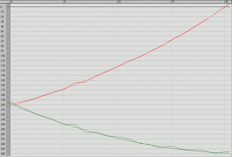
Figure 4. Graph of x and y positional movements of original and calculated camera.
A digital camera (AGFA ePhoto 1280) was used to take pictures outside the computer science building of the university. The ground in front of the university is decorated with cobblestones arranged in a grid pattern. It can be seen from this example that it is usually possible to find characteristic points in the outdoor environment which can be used as markers, therefore it is not always necessary to change the environment by placing artificial markers. Naturally, higher level computer vision image processing would be needed if –as part of an outdoor augmented reality application– these characteristic points would need to be continuously tracked in real time.
The width of the “grid” was measured (~385 cm) on site. Also, roughly estimated camera positions were noted with a precision of about 1m. The pictures were recorded with a resolution of 1024x768 using the lowest compression setting of the camera. Luckily this camera matching program is not restricted to using non-coplanar points, which would have made taking measurements difficult in three dimensions, and would have required the placement of artificial physical markers.
In this test, since the markers cannot be precisely identified based on their color, the needed 2 dimensional image coordinates were specified manually. The relative 3D position of points and the approximate preliminary camera parameter estimates were also given.
The precisely calculated camera parameters were used to render the following picture (Figure 5.).
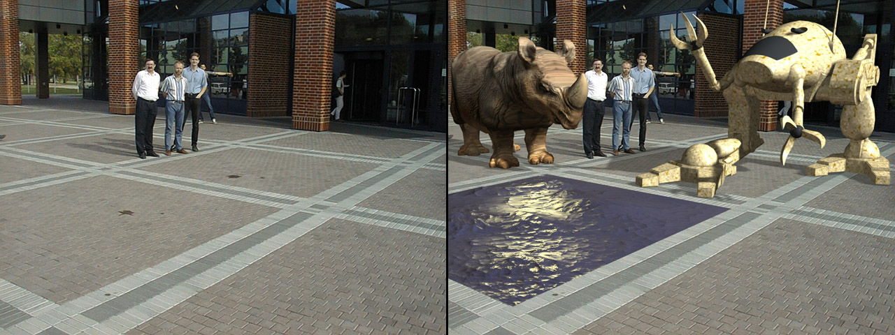
Figure 5.: Outdoor images (original, augmented)
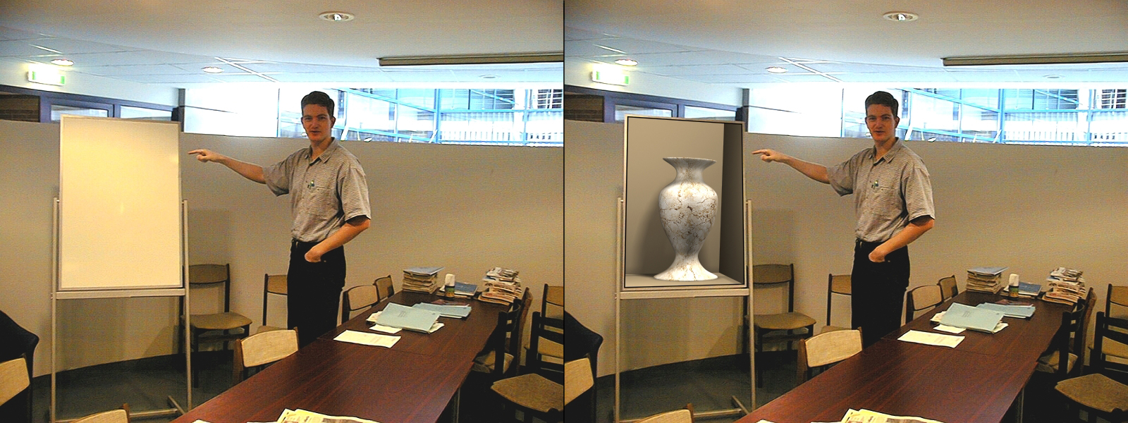
Figure 6.: Indoor images (original augmented)
Pictures were also taken inside the building. In this example (Figure 6.) the corners of the whiteboard were used as markers. In this example the whiteboard was given virtual depth and a model of a vase was positioned inside the virtual presentation.
A semi-professional VHS video camera was used to record video footage with random camera movements. White paper squares (width 5cm) were placed on the four corners of a table, and the width of the table was measured (70 cm). The ”scene” was filmed with a handheld camera, therefore no information about the cameras initial position or movement was used. The VHS material was digitized into the computer with half-PAL (384x288) resolution, using hardware square pixel conversion.
In this test Newton-Raphson method’s global convergence was tested, by giving highly irrealistic data as initial estimated camera parameters. It can be seen from the data and the image produced by the estimated camera position, that extremely imprecise initial parameter estimates can be given. After the camera position of the first image of the sequence was precisely calculated with 50 iterational steps, the system automatically tracked the markers, and calculated the camera parameters with only 10 iteration steps. (Figure 7.)
In this test, the virtual camera’s motion cannot be numerically compared with that of the original camera, but judging by the smoothness of the parameter changes from frame to frame and from the composited video sequence, the system produces highly satisfactory results.
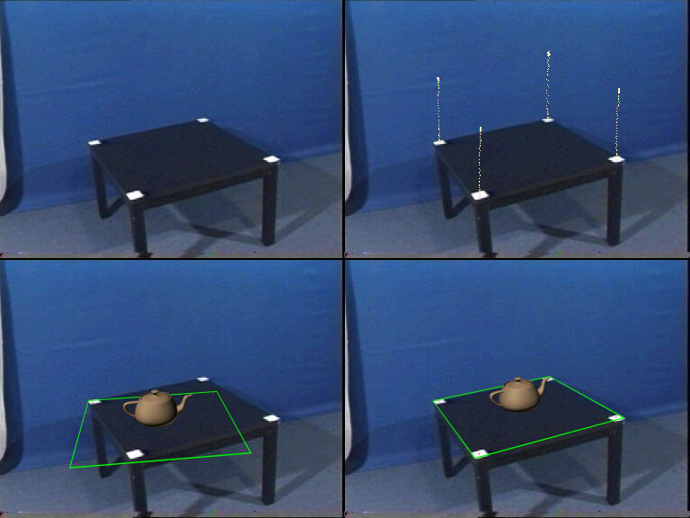
Figure 7.: 1st frame of video test sequence
(original image, marker position tracking over sequence,
image from estimated camera position, final augmented image)
The system, in its present status, has several strengths and a few weaknesses. Both are mainly the results of the implementation.
The ”plug-in” architecture enables the user to use a powerful 3D program for modelling and rendering with the camera-matching program working as an integrated module with an easy to use interface. This environment however limits the use of the camera-matching system to offline post-production work. The MaxScript language is slow compared to low level programming languages, due to its runtime interpreter. The renderer of the 3D environment is powerful, but it is also very time consuming.
Nevertheless the system’s requirement of the use of only 4 unrestrictedly positioned markers offers advantages compared to commercial camera-matching programs which utilise a similar approach to calculating camera parameters.
Presently, a real-time implementation of the system is under development. Making the system work in real-time requires the development of a 3D engine having modelling and/or model importing functionality. Also a real-time video capture, image processing, and compositing system have to be used. The most time consuming part of the present system is the marker tracker, and the renderer. It could be possible to integrate a marker-tracker within the video digitizer hardware subsystem of a future implementation. Luckily, inexpensive three dimensional real-time graphics systems are already widely available today. Unfortunately a real-time 3D engine does not offer the picture quality produced by off-line renderers.
Vision based camera matching has several advantages over other methods. It offers one of the best solutions to providing viewpoint synchronisation for mixed reality applications. With the use of higher resolution cameras, displays and faster processors vision based systems will fulfil all the requirements for augmented reality use; speed, accuracy, portability, operation anywhere in any environment.
This work has been supported by the National Scientific Research Fund (OTKA ref. No: T029135).
[1] Radamec Broadcasting Systems Ltd.:
www.radamec.co.uk[2] Thoma Broadcast:
www.thoma.de[3] Ronald T. Azuma: A Survey on Augmented Reality, in Presence: Teleoperators and Virtual Environments Vol.6, No.4, pp. 355-385, August 1997
[4] Karl Kraus: Photogrammetrie, Dümmlers Verlag, Bonn 1994.
[5] Numerical Recipes in C, Cambridge University Press, 1988-1992.
[6] Klinker et al.: Confluence of Computer Vision and Interactive Graphics for Augmented Reality, Presence: Teleoperators and Virtual Environments, Vol 6, No 4, pp. 433-451. 1997
[7] U. Neumann, Y. Cho: A Self-Tracking Augmented Reality System, Proceedings of ACM Virtual Reality Software and Technology ‘96, pp. 109-115, 1996.
[8] J.P. Mellor: Enchanced Reality Visualization in a Surgical Environment, Master’s Thesis, Dept of Electrical Engineering, MIT, 1995.
[9] A. Azarbayejani, A. Pentland: Recursive Estimation of Motion, Structure, and Focal Length, IEEE Transactions on Pattern Analysis and Machine Intelligence, Vol. 17, No. 6, June 1995.
[10] T.J.Broida, S. Chandrashekhar, R. Chellappa: Recursive Estimation from a Monocular Image Sequence, IEEE Transactions on Aerospace and Electronic Systems, Vol. 26, No. 7. July 1990.
[11] Jiøí Walder: An experimental system for reconstructing a scene from the image sequences produced by a moving camera, Proc. CESCG '99, Budmerice, Slovakia, pp.139-148, 1999.
[12] E. Natonek, Th. Zimmerman, L. Fluckiger: Model Based Vision as Feedback for Virtual Reality Robotics Environments, Proceedings of VRAIS ’95, pp.110-117, 1995.
[13] L.Szirmay-Kalos: Theory of Three-Dimensional Computer Graphics, Publishing House of the Hungarian Academy of Sciences, Budapest, 1995. http://www.iit.bme.hu/~szirmay/book.html