Gábor Szijártó
gabor.szijarto@freemail.hu
www.geocities.com/gabsprog/
Computer Graphics Group at the Department of Control
Engineering and Information Technology
Budapest University of Technology and Economics
Budapest / Hungary
This paper presents a face modelling system that can define and manipulate the geometry of a human face in real-time. The system uses a three-level representation that allows the user to modify the parameters using intuitive commands on the highest level, while the geometry is described by Bezier patches and triangles on the lowest level. A critical design issue of such a system is to find a reasonable compromise between visual realism, ease of control and rendering speed.
Keywords: human face, modelling, interactive graphics, parametric surfaces, surface continuity, anatomy.
Evolution of desktop computers has made it possible to model and animate the human body in real time. This paper presents a modelling system that can define 3D geometric models of the human face. The modelling system takes advantage of the fact that the development of display adapters accelerating 3D rendering has improved the possibilities of real-time modification and rendering. Hardware support for rendering is essential, since tens of thousands of triangles need to be rendered when a face model is edited.
The key element of face modelling is to find a suitable data structure for the representation. The representation determines the possible ways of modifications and also the rendering realism. First, modelling approaches proposed by the previous work are surveyed and their strengths and weaknesses are analysed, then a new hierarchical technique is presented. The requirement of the hierarchical representation stems from the inherent structure of the face since it consists of smaller elements, such as the nose, the mouth, the eyes, etc. These are still complex components, so further partitioning is also sensible.
A human face modelling software can be used in many different application areas, for example, in police graphics, plastic surgery, hairstyle and makeup design, low bandwidth video conference and virtual reality. For police graphics, the primary goal is the good visualization. Currently the two most often used techniques in this field are the freehand drawing and the composition of photos using different slices for the eyes, the nose and the mouth. If face modelling software is used, graphics can be created in a shorter time and the visual quality is improved. 3D rendering provides the possibility of showing the face from various points of view, which is impossible with current handmade pictures.
For hairstyle and makeup design, the primary objective is also the good visualization. Customers can easily choose the best style for themselves, without any irreversible destruction or unwanted changing their hair cutting.
This section reviews the existing techniques of human face modelling, and their advantages and disadvantages are examined considering the visual quality and the modelling capabilities.
This technique is very popular in police graphics. The face is made up from photos of various parts of real faces. This is an easy-to-learn manual task, although it is hard to master. Unfortunately, the result is always 2D only. Storage and retrieval of the photos used in the face reconstruction poses serious problems.
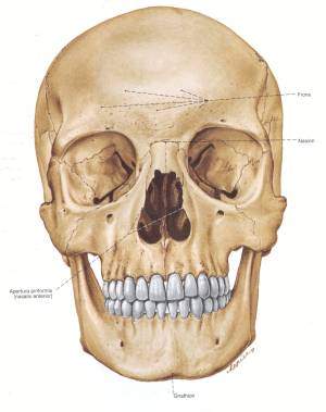
Modelling the real anatomy of the human face is the most realistic modelling technique. However, modelling bones, muscles and skin requires an extensive knowledge of anatomy [6]. The definition of bones is simple since their shape is fixed, but muscles are much more complex. Muscles are soft tissues, therefore their shape can change depending on the relative position of bones, other muscles and the tension in muscles. Each muscle is connected to bones at two points. If those bones move, the muscle is tensed or eased. The skin is the outermost element of this structure. Its shape depends on its softness, fatness, and the shape of the underlying muscles.
Figure 1: Skull (left) and muscles position (right) of human face.
The most attractive property of this technique is realistic modelling. Thus it is easy to find the right parameter when a given attribute of the face needs to be modified. The visual quality is also very good. On the other hand, the rendering time is very long, even minutes or hours. Setting out a model based on anatomic details is a long and complex process, therefore easier and faster techniques are needed.
Maybe it is the simplest technique considered so far. Point based modelling is based on the definition of the skin as a group of points, and this group is modified by particular functions. In fact, this technique is a simplification of the previous one, but models the skin only. Now the points of the skin are modified by some simple functions instead of anatomy rules. This approach may yield some artifacts, thus the careful definition of functions and parameters is very important.
A function modifies groups of points to various extents. Since each function influences many points and each point is controlled by many functions, the management of this structure can be very complex. However, many points of the skin belong to smooth patches that can easily be created as parametric surfaces. This idea leads to the next paradigm, called the surface based modelling.
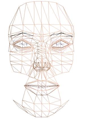

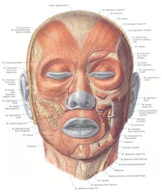
Figure 2: A comparison of surface based modelling (left) and point based modelling (right).
Surface based modelling resembles the previous one, but this method manages all points via surfaces. A surface collects hundreds of points, thus managing the model is easier (Figure 2).
The skin is defined by the main control points. Creating the parametric surface from the control points usually requires the calculation of surface tangentials, too. Thus the time spent calculating a single point is longer, but there are less points than in the previous model. On the whole, calculation is a lot faster. Two techniques exist for managing the surfaces, called the static and the dynamic model.
This technique uses a fixed number vertices at fixed topological positions. Since the sets of neighbours of each point are constant, the polygon net of the model is predetermined. An advantage of this technique is its simplicity. When changing parameters of the face, only the main control points need to be modified, thus it is easy to morph from one face to another. However, such capability is rarely required. The main drawback of this technique shows up when representing humps, scars or other unusual objects on the skin is desired. If there are too few points for satisfactory representation of these properties, the surface appears wrinkled or angular in an unnatural way.
Instead of a constant number of main control points, this technique allows more freedom by adding control points where the face is less smooth. It yields better visual quality than the static model, but the polygon net needs to be regenerated at each modification of the face, and the regeneration process is not easy.
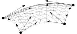
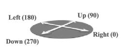
Figure 3: Control points of Bezier surfaces (left), and the tangential plane of a main control point (right).
Each point has a position in the 3D space and a tangential plane that is determined by four vectors. These vectors define a coordinate system (Figure 3). The names of vectors are the following: right (0 degree), up (90 degree), left (180 degree) and down (270 degree).
Each surface has four indices that refer to the main control points. The number of surfaces aligned with a specific main control point is not necessarily four, furthermore, their edges do not necessarily meet at right angles. Therefore the surfaces specify the angles between their edges running into a given main control point.
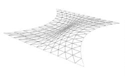
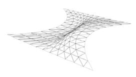
Figure 4: Piled up points (left) and an undesired wrinkled surface (right).
Bezier surfaces have 16 control
points. Calculating the 12 points on the edges is easy, but calculating the
four points in the middle of the surface patch is more involved. The simplest
way is to add the two neighbouring edge vectors (![]() ). However, when the main control points are
too close to each other, the points calculated in this way can pile up in the
middle of the surface patch (Figure 4). In extreme conditions the topological
positions of middle points can even be swapped. This may result in undesired
wrinkled and corrupt surfaces (Figure 4). Therefore a more flexible calculation
method is required.
). However, when the main control points are
too close to each other, the points calculated in this way can pile up in the
middle of the surface patch (Figure 4). In extreme conditions the topological
positions of middle points can even be swapped. This may result in undesired
wrinkled and corrupt surfaces (Figure 4). Therefore a more flexible calculation
method is required.
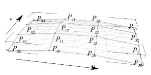
Figure 5: The control points of a Bezier surface.
To eliminate the piling up
problem, the middle points are calculated as weighted sums of the corner
vectors. The weighting factors effectively project the corner vectors onto the
middle line of control points (![]() ,
, ![]() ,
, ![]() ,
, ![]() ).
This avoids swapping the middle points, thus prevents the
undesired wrinkles in the patches. The following equation defines
).
This avoids swapping the middle points, thus prevents the
undesired wrinkles in the patches. The following equation defines
![]() using this weighting
method:
using this weighting
method:
![]()
The control points may not uniformly be distributed. This allows for a further degree of freedom in modelling. The relative lengths of the corner vectors are defined for each point. This solves problems for rectangle surface patches, but sometimes triangle patches are necessary. If two adjacent main control points (say, P00 and P03) are united, then the patch degenerates to a triangle. However, at the united point visible artifacts may appear because of degenerate null area triangles (Figure 6). Triangles can also be subdivided to smaller triangles (Figure 6). Unfortunately, in this case the horizontal and the vertical subdivision detail levels are not independent.
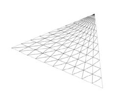
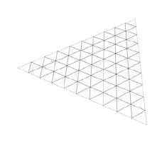
Figure 6: A triangle build of rectangular patches (left) and of small triangles (right).
During modelling, the user specifies parameters in order to alter the geometry of the face. If the user had to directly modify the point parameters such as 3D position, they would have to solve a very complex problem and this approach is clearly impractical in modelling. Therefore the program shows a different set of higher level conceptual parameters instead, which are easier to understand for the ordinary user. An example of such parameter is the size of the nose.
However, these high level parameters are not optimal for rendering, thus it is not worth storing them directly. Neither the main control points are appropriate for this kind of primary representation. Considering these facts, a three-level structure of parameters is implemented, consisting of the conceptual parameters on the top level, the stored parameters on the second level and the parameters of main control points on the third level. The program stores the second level parameters only, therefore the other levels of parameters are calculated from them. The user can modify the top level parameters, the second level parameters are calculated from those (Figure 7).
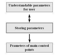
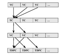
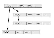
Figure 7: The three-level architecture (left), VC, TC and TDPC relation (middle) and HGC tree (right).
To manage the geometric structure, the following codes are used: tool code (TC), variable code (VC), hierarchy code (HGC) and three-dimensional point code (TDPC). Except for HGC, each code is assigned to a level. The TC is on the first level, the VC is on the second level and the TDPC is on third level. The HGC is a helper for better performance. A TC code identifies a parameter that is visible to and controlled by the user. When the parameter is displayed, the program calculates its value from some parameters of VC codes. After modification the program recalculates the new parameters of VC codes (Figure 7). A VC code represents a parameter and a HGC code. The parameter stores geometry data of the face. These parameters will be discussed in detail in the following section. A TDPC code identifies the position and the tangential plane of a main control point. HGC codes define the main control points influenced by a VC parameter. Thus they accelerate recalculation of main control points since unchanged parameters are not recalculated. Because of the hierarchical nature of the face, HGC codes are stored in a tree. Each tree node contains a HGC code and a list of TDPC codes that specify the main control points to update.
There are three types of functions for managing the three-level architecture: write-out, modifying and TDPC functions. Before the TC parameters are displayed for the user the program calculates them by write-out functions. Each TC code has a modifying function that uses some VC parameters. After TC parameter modification the program calculates the new VC parameters. Each TDPC code has a TDPC function that calculates the parameters of the main control point from the new VC parameters. These functions relations are displayed in Figure 8.
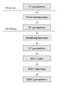
Figure 8: The parameter modification diagram.
VC parameters stored by the program define geometrical properties such as coordinates, angles and distances. These parameters have clear meanings for the software developer, and they are independent of each other.
Some parts of the face can be modified independently of other elements. The shape of the nose, for example, is not related to any other parts of the face. On the other hand, there are parts that are largely influenced by the adjacent elements. An example of such part is the cheek that is very much controlled by the nose, the eye, the mouth and the chin. This kind of interference between face elements is implemented in the top level parameters.
The human face is built up in a hierarchical way. Each part (eyes, nose, etc.) and their subparts have their own hierarchical coordinate system. This structure makes the calculation of VC parameters easier. For example, only the mouth coordinate system needs to be altered when the mouth is moved.
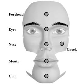
Figure 9: The top of the face hierarchy.
At the top of the hierarchy there are six parts: a chin, a mouth, a nose, eyes, a forehead and a cheek (Figure 9). All elements have subparts. Here only the subparts of the nose are discussed in detail.
The nose is one of the most complex parts of the human face. There are a lot of geometrical properties and restrictions regarding the nose. These properties can be represented on the VC level most effectively. Thus the upper level functions can be made simple.
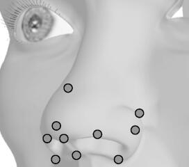
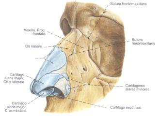
Figure 10: Characteristic points of the nose (left) and the anatomy of the nose (right).
The nose has 14 characteristic points as shown in Figure 10. Two of them are inside the nostrils and two are hidden on the right side of the nose. These characteristic points determine all parts of the nose like the nostril, the tip of the nose and so on. The main control points of the surface patches are calculated from head points. The positions of surface patches are displayed in Figure 11. The image also shows that areas of more detail are tessellated further.
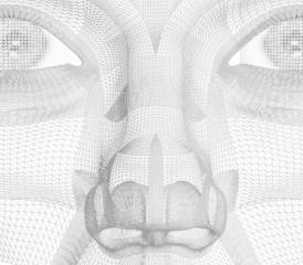
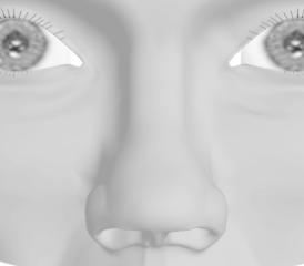
Figure 11: Surface position of the nose (left) and a shaded nose (right).
The FaceMaker program has been implemented in Visual C++, runs on MS Windows 9x, ME and 2000 and uses Win32 [3][4] and Direct3D [5] for rendering. Figure 12 shows a screenshot of the program.
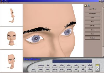
Figure 12: A screenshot of the FaceMaker program.
The program interface is straightforward. There are four viewports of the face, a big and three smaller ones. The face can be rotated, paned and zoomed in each viewport. There is a main bar below, which contains a message display area and buttons for the global functions. At the right side of window there is a tool bar for tools modifying the face.
This paper presented techniques for human face modelling, which are suitable for interactive applications. The developed methods of face parameter storage and modification provide visually attractive results. The proposed techniques and a framework of the editing program have also been implemented.
Future work will concentrate on completing the geometry model of the face, especially the cheek, and implementing other modifier functions. These new modifier functions may require further enhancement of the face geometry. Other possible improvements of the program can concentrate on more sophisticated visual details, textures and bump mapping, on OpenGL support and on adaptive triangulation of surfaces to speed up rendering.
This work has been supported by the National Scientific Research Fund (OTKA ref. No.: T029135) and the IKTA-00101/2000 project. Parts of the geometric model have been built using Maya donated by AliasWavefront.
[1] Alain Watt, 3D Computer Graphics Third Edition, published by Addison-Welsey, 2000
[2] Alain Watt and Fabio Policarpo, 3D Games Real time Rendering and Software Technology, published by Addison-Welsey, 2001
[3] Charles Petzold, Paul Yao, Programming Windows 95, published by Microsoft Press, 1996
[4] Microsoft Platform Software Development Kit, © 1985-2000 Microsoft Corporation. All rights reserved.
[5] DirectX 7 Programmer's Reference, © 1995-1999 Microsoft Corporation. All rights reserved. http://www.microsoft.com/directx/
[6] Reinhard. Putz, Reinhard Pabst Sobotta, The Atlas of the Human Body. Volume 1. Semmelweis Kiadó 1994
[7] László Szirmay-Kalos: Theory of Three Dimensional Computer Graphics, Akadémiai Kiadó, Budapest, 1995.