Data Acquisition for VIRTUAL OLD PRAGUE

Petr Bouchner
pedro2@volny.cz
Department of Computer Science and Engineering
Czech Technical University
Prague / Czech Republic


Abstract

The paper describes main principles and guidelines for creation of realistically looking virtual town. It is focused mainly on the work on the project “Virtual Old Prague” and usage of original authoring tools and additional third party applications. It depicts special procedures and shows pit-falls and advices within the work. Methods and procedures described here can be successfully applied on creation of any kind of Internet based virtual world.

Keywords: interactive VRML, VRML Internet engine, virtual town, “Virtual Old Prague”.

1. Introduction

It is always a great challenge to create virtual image of the real world. Usually it means very interesting work, but sometimes one can easily get into pitfall or spend a lot of time with investigation of “blind ways”. This paper should introduce those procedures, which we approved during our work and which should speed up the process of the construction of virtual town. In the section number two there are described the main parts and functions of VOP system. It is necessary to be familiar with the system, if we want to work efficiently. Next section shows concrete procedures (and useful advices) for photographing, image processing, developing of VRML models, and putting it all together into one virtual world.

2. Basic system information

Project of Virtual Old Prague (VOP) was created at the MFF of Charles University in Prague during years 2000/2001 (see [1]). It was aimed to “transport” interesting parts of our capital into virtual environment, so that these would be accessible to wide variety of people over the world via the Internet. People from developing team created a complete set of authoring tools and utilities, which allows providing any virtual town via the Internet. The tools are available to download from VOP project home page [1], accompanied with full user documentation and source code.

The whole project is composed of the following parts:

· server side:

· the database MySQL and supporting stuff
· PHP scripts for VRML worlds issuing

· client side:

· web-pages
· Java applets and ECMA scripts for VRML browser driving
· administration tools for database · tool for city editing
· tools for creating VRML models of houses

An advanced bitmap editor is the only additional tool required for the work on virtual town, which is not supplied within this “package”. The Adobe Photoshop 6 is advisable due to its supreme set of transformation filters. It is possible to use any other advanced free of charge bitmap editor as a substitute (e.g. Gimp).

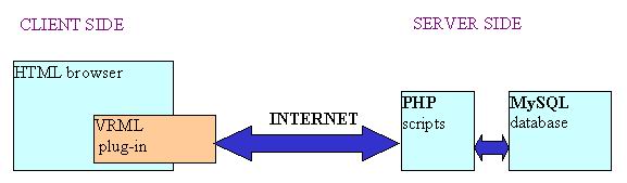
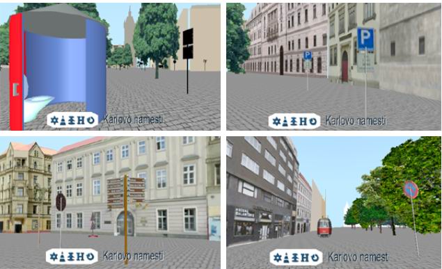
Fig.1: System diagram

Figure 1 depicts how the system works. Several clients are connected to the server, which provides services for the database and dynamical scripts which issue client’s browser with the actual VRML world. Note, that PHP and MySQL were chosen due to their free of charge distribution, so the possible town creator does not need to comprise any additional expenses. (For more details on VRML language see [2].)

2.1 Authoring tools

Several tools and utilities were used during our work. Besides those common ones (bitmap editors, text editor, server administration and secure data transfer tools, database utilities) we use three novel tools, especially created as a part of VOP project.

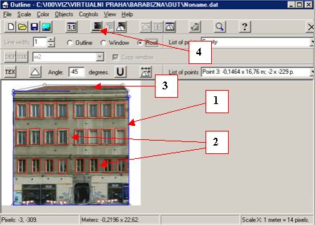
2.1.1 OUTLINE and LOD

OUTLINE is a very interesting application, which helps a lot with modelling of facades. Facades (gable walls) are basic elements of the virtual town. Streets are composed just of sets of facades. An intersection of the streets creates a corner. The polygonal object (silhouette), which represents one house in the virtual world, is generated in 3 levels of detail (“LOD”). Such decomposition of one object into more models with different complexity can significantly improve performance of the whole system. The larger is a distance from observer, the less complex object is viewed. For more details on general approach of “LODs” see [4].

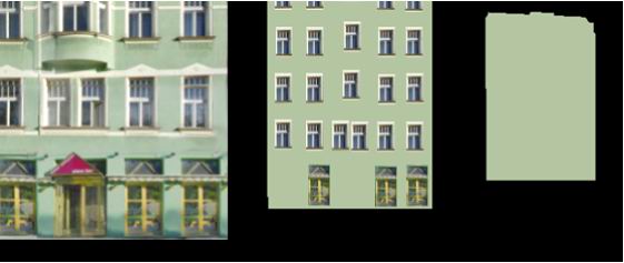
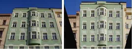
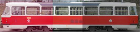
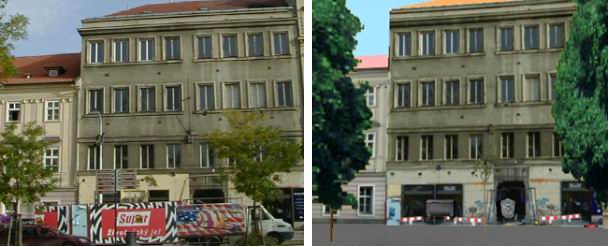
Fig. 2: Three levels of detail of the same facade

Figure 2 shows comparison of all three LODs. (Note, that normally they cannot be seen at once within one view.) The left most one represents a full detailed texture (an observer is close and he/she wants to see the detailed object). The middle one is a composition of a silhouette (painted with an average colour) and low-resolution separate textures of windows. That right most view shows the less detailed object – a silhouette painted with an average colour (i.e. a colour which represents some good approximation of the original texture). Such arrangement speeds up the performance a lot. Mainly the machines with slower access to the Internet take advantage of the fact that textures in distance do not need to be loaded before the observer gets closer. More detailed view on the usage of OUTLINE will be focused in section 3 - modelling.

The application called LOD is a utility, which is not needed for town building itself. It is intended to help when revising output of OUTLINE before this is issued into the town database. LOD groups up all the “levels of detail” of the facade, so that it is possible to see it as a single object in a VRML browser.
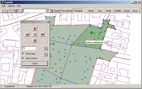
2.1.2 MAPEDIT

MAPEDIT is a specially designed application, which builds up the virtual town structure in a database. It is directly connected to the server and possesses functions like differentiation of the space into sectors, visibility definitions and the main task - placement of the facades and other VRML objects. More details concerning work with MAPEDIT are placed in section 3.

3. Work procedure

In following paragraphs the most important steps and advices of the workflow will be described (see the figure 3, which shows main phases of the work).

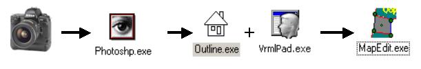
Fig. 3: Basic stages of workflow

The diagram on figure 3 is self-explanatory. Taking pictures of all modelled objects is followed by photo editing and retouching. Then the silhouette creation tool (OUTLINE) is used, accompanied with hand tuning of VRML code (VrmlPad was used in our case, but any text editor would serve as well). After all the silhouettes are worked out, they are ready to be imported into our virtual world via MAPEDIT.

Next subsections will depict procedures we successfully used, step by step.

3.1 Taking pictures

The very first task in creation process is to take pictures of the given set of buildings and optionally other objects, which should be included into the virtual world. It is not as simple task as it seems to be. It is recommended to use a digital photo camera due to its low work expenses (we photographed hundreds of pictures) and also very straightforward and fast connection with the computer.

The main rules which need to be respected, could be summed up as follows:

· Photograph under suitable light conditions. When the sunshine is too bright, hard shadow will appear on pictures. Lack of light causes lost of details.
· The higher focus length, the better. Too much of zoom causes spherical and perspective distortion.
· It is not necessary to take the whole object in one picture, better is to avoid obstacles using different points of view (but think ahead of further composing those parts together).
· If it is not possible to photograph all the parts of the object, take more detailed pictures of the parts, which are similar to those hidden ones. They could be good substitutes in the retouching process (see the picture editing section for details).

3.2 Picture editing

All the editing was done with Photoshop 6, but any advanced bitmap editor should serve as well (only the filter names perhaps will not match).

3.2.1 Transformations

First transformation, which should be applied before any other, is removing of a spherical incurvation caused by camera lens. We successfully used the spherize filter with negative value of spherization ratio.

Second indispensable step is an “ortogonating of perspective projection”. When the photographed object is big enough, a perspective deformation becomes more and more noticeable. The texture requires to be mapped onto the polygon “perspectiveless”. The perspective, skew and distort tools are suitable to correct it. Figure 4 illustrates it well.

If the object is too big to fit in one photo it needs to be photographed in more shots. It is also advisable to take more shots instead of zooming-out (it prevents significant distortions). When taking series of pictures it is always recommended to maintain the relative distance and mainly the same relative angle. Some digital cameras have special function for panoramic pictures; this can be helpful. Figure 5 shows a composition of three shots. The colour difference (stripping) is caused by changed light conditions between particular shoots.

Fig. 4: Photo before and after application of view transforming filters

Fig. 5: Grouping up of separately taken pictures of one object

3.2.2 Retouching

That most laborious section of the work was retouching. We spent about 70% of our work on the project with retouching. There is no general straightforward way of how to do it best. Basic tools for retouching are: lightening, darkening, finger-painting and mainly copy&paste of different shapes of marquee.

Fig. 6: Reality (left) vs. Virtual reality (right)

Figure 6 shows the original photo of the building, which was partially hidden by obstacles (the left picture) and the resulting worked out texture, mapped on the building gable wall in virtual reality (the right picture). This right picture is a snap shot from a VRML browser (see [2]). Parts, which were not able to photograph, are “made-up” using the methods described above. Note, that the whole texture is only 30 kB large!

3.2.3 Exporting Textures

Size of the final texture is a compromise between quality (i.e. resolution and colour depth) and requested speed of the overall system. VOP is an Internet application, so the lower the size is, the better. Our textures are in PNG format (32b palette colours) of size around 250x250 pixels with colour count from 32 to 128. It is recommended to fit the textures into 2n rectangle – it is more suitable for 3D accelerators.

3.3 Modelling

3.3.1 Facades (OUTLINE)

Procedure of creation of facade is as follows (see Fig. 7 for reference): First, the shape of polygon is defined as a painted contour (1), then windows (2) are chosen for second LOD. It is also possible to define a roof in the same manner as in the case of silhouettes (3) and finally to choose an average colour for untextured polygon in the third LOD (4).

Fig. 7: OUTLINE desktop

3.3.2 Another objects (VRML)

Since the VOP engine keeps all the functionalities of VRML [2], any kind of VRML object can be involved into the virtual town. We decided to create set of static objects (trees, shrub, signage, statues) and two dynamic objects. Nature gives the virtual world more realistic look. It is important to model them conscientiously. Figure 8 illustrates two approaches of modelling trees. The young tree in front is composed of a cylindrical trunk; two perpendicular squares covered with masked texture constitute a treetop. The leafy tree in the central part is a rectangular billboard covered again with masked texture (more details on billboard approach see in [5]).

On the Figure 9 there is “interactive WC” which reacts on avatar’s hand and an authentic “CKD TRAM” which goes through CHARLES SQUERE in an L-pattern route.

Fig. 8: Two different approaches of tree representation

Fig. 9: Dynamic models in VRML

The WC cabin is built up from primitives, meanwhile the tram mesh is composed of set of about 100 triangles, textured with 256x256 PNG picture (PNG format allows transparency map – see pantograph).

3.4 World creation

MAPEDIT is used for final world creation. It is a 2D map-like editor, which enables to import all the objects into the virtual town and set up global conditions. Figure 10 shows the working desktop of MAPEDIT. Sectors are defined by closed set of contouring edges (borders). Each vertex contains information about its elevation. Each edge contains information about its functionality (wall flag for collision detection, end of the world and so on). Bigger points (nodes) represent any VRML object imported into the town.

Fig. 10: MAPEDIT desktop

Off-line visibility function is used, to allow easy estimation on what sectors will be rendered. The problematic objects are those which are pending between several sectors (i.e. our TRAM). They need to be visible from all the points along their route. We took advantage of the fact that the neighbouring sectors are always visible from each other. We assigned the root sector of the tram (where the tram starts its tour) as a neighbour of all the sectors, which are crossed by its route. Only one restriction should be done: The tram root sector should contain as few object as possible. An empty sector would be the best solution. Due to the “neighbour” visibility approach, it is rendered every time the observer enters the sectors, which are crossed by the tram route.

4. Conclusions

The virtual model of the realistic town is rather complex task requiring a certain level of know-how in the area of computer graphics. We have shown the system based on VRML, which we successfully used for the virtual Charles Square in Prague. The described algorithms, advices and guidelines fit perfectly to VOP system, but they are mostly valid in general. Illustrative pictures and figures depict the approaches and procedures, which led our work to good result - creation of realistically looking virtual town, accessible via the Internet with acceptable performance on low cost systems.

5. References

[1] VOP at the MFF of Charles University in Prague (with full documentation): http://www.ms.mff.cuni.cz/vsp/

[2] The Virtual Reality Modeling Language.International Standard ISO/IEC 14772-1:1997, http://www.web3d.org/technicalinfo/specifications/vrml97/index.htm

[3] VOP at the FEE of Czech Technical University in Prague: http://netra.felk.cvut.cz/~vsp

[4] Pajon, J. L., Collenot, Y., Lhomme, X., Tsingos, N., Sillion, F., Guilloteau, P., Vuyslteker, P., Grillon, G., David, D.: Building and exploiting levels of detail: an overview and some VRML experiments, in 1995 Symposium on the Virtual Reality Modeling Language, VRML '95, San Diego, California, December 14—15, ACM Press, 1996

[5] McReynolds, T., Blythe, D.: Advanced Graphics Programming Techniques Using OpenGL, in SIGGRAPH 2000 Course 32, Course Notes, 2000


APPENDIX

Set of snapshots from Charles Square