Rigid Body Collision Response

Ladislav Kavan1

Abstract

In many virtual reality applications it is necessary to simulate the interaction among solid objects. One of the basic requirements is to ensure a non-penetration of rigid bodies. We show algorithms for detecting a collision of moving bodies along with the exact time of collision determination. Next we present a method for computation the post-collision velocities and positions of colliding objects. In our approach we exploit the laws of classical mechanics, however the physical accuracy is not the goal. We sacrifice the accuracy in exchange for simple and real-time algorithms.

1  Introduction

Although the non-penetration of rigid bodies is quite common in the real world, in virtual environments the contrary is true. The reason is that the dynamics simulation is not an easy task; it involves several different problems. The first is the collision detection, which is considered the bottleneck of the simulation [15]. Moreover, classical collision detection, as we will refer to static collision detection, does not count with the objects motion. We demonstrate that considering the motion of the rigid bodies is necessary for correct collision response. After detecting the collision, the dynamic state of the colliding objects must be changed in order to avoid the inter-penetration. The change depends on the type of the collision and on the parameters of the colliding objects.
The very general goal of a rigid body dynamics simulation is to generate a movement of rigid bodies when external forces are given. This requires a numerical method for solving differential equations as presented in [3]. However we are interested only in the non-penetration constraints which we will ensure in rather kinematic way. We do not consider the forces that are responsible for the objects motion2.
In this paper, we do not discuss neither the static collision detection, nor the simulation of the external forces. We present a method for solving the collision response for only two colliding objects. Although the physical correctness is not our goal, we account for different rigid body's mass properties and the laws of mechanics to achieve more plausible results. In section 2 we present a brief outfit of rigid body mechanics, which we need in next sections; for more detailed explanation see for example [3]. Section 3 describes the problems of static collision detection and proposes a simple algorithm for dynamizing the collision detection. The collision response itself is discussed in section 4. Finally, in section 5 we present an application that implements these methods.

1.1  Related Work and Our Contribution

The static collision detection is well developed, the methods differ mainly by the bounding volumes they use. The Axis-Aligned Bounding Boxes [16] may seem obsolette, but they have certain properties useful for deformable models (quick tree re-computation after deformation). Two modern competing bounding volumes are Discrete Orientation Polytopes [10] and Oriented Bounding Boxes [8]. Dynamic collision detection is studied in [7]. They reduce the dynamic collision detection to a root finding problem, which is solved by numeric methods (namely regula falsi).
Also concerning collision response a lot of work has been done, but no uniform approach is the best in general. See [1] for a survey. Physically based collision response together with dynamics simulation (via numeric solution of differential equations) is explained in excellent tutorial [3,4]. Besides the colliding contact, it involves also a resting contact treatment, which is one of the most difficult problems. [3,4] show a physically based solution using static (contact) forces. These forces are computed with quadratic programming. Another method for the contact forces computation is based on the linear-complementarity problem (LCP) [2,5]. [15] proposes an alternative to static forces by so called micro-collisions - many small impulses that are used instead of static forces.
Well readable articles intended for game developers are [11,9]. They cover mainly the basic physics and colliding contact. An interesting recent result is described by [13]. They formulate the dynamics simulation as an optimization problem and solve it by quadratic programming.
Our contribution is mainly in simplifying complex approaches. This is the case of the dynamic collision detection (section 3) and resting contact (4.2). The application (5) is of course also original. On the other hand the colliding contact (4.1) as well as the rigid body mechanics (2) have already been described by other authors [3,4].

2  Rigid Body Mechanics

A rigid body is a solid object that can not be deformed in any way - its shape does not change during the simulation. If we denote the body's volume V Í R3 and density function r: V ® R we can define the body's mass
m = ó
õ


V 
r(r)dV
(1)
and the center of mass
ó
õ


V 
rr(r)dV

m
(2)
Vectors relative to the center of mass will be denoted by subscript c. The moments of intertia are defined as follows
Jxx
=
ó
õ


V 
(rc,y2 + rc,z2)r(rc)dV
Jyy
=
ó
õ


V 
(rc,x2 + rc,z2)r(rc)dV
Jzz
=
ó
õ


V 
(rc,x2 + rc,y2)r(rc)dV
Jxy
=
ó
õ


V 
rc,x rc,y r(rc)dV
Jxz
=
ó
õ


V 
rc,x rc,z r(rc)dV
Jyz
=
ó
õ


V 
rc,y rc,z r(rc)dV
where rc = (rc,x, rc,y, rc,z) is a body space vector relative to the center of mass. The moments form together an inertia tensor
J = æ
ç
ç
ç
è
Jxx
-Jxy
-Jxz
-Jxy
Jyy
-Jyz
-Jxz
-Jyz
Jzz
ö
÷
÷
÷
ø
(3)
All the integrals are computed in the body space relative to the center of mass. In computer graphics we usually work with solids represented by polygonal meshes. The integration over such objects can be efficiently computed using the divergence theorem; the procedure is described in [14].
Position of a rigid body in space is characterized by a translation vector and a rotation. The rotation can be represented by Each of this representations has its advantages and disadvantages. Conversions between them are described in [6]. Any of these representations requires only 3 scalars to store which sums together with the translation vector to 6 degrees of freedom (DOF).
The placement of a rigid body is advantageously described relatively to its center of mass. In a world space coordinate system in time t we define the position of the center of mass rc(t) and orientation given by rotation matrix R(t). Then the vector rb in body space maps to the vector rw(t) in world space by formula
rw(t) = rc(t) + R(t) rb
(4)
The actual inertia tensor I(t) for a rotated body is computed from the body's space inertia tensor by equation
I(t) = R(t)JR(t)T
(5)
as derived in [3].
The movement of a rigid body can be decomposed to a linear velocity vc(t) of the center of mass and an angular velocity w(t) relative to the center of mass. w(t) is the unitary axis of rotation multiplied by the angular velocity. The velocity v(t) of a point that has world space position r(t) is computed as
×
r
 
(t) = v(t) = vc(t) + w(t) ×(r(t) - rc(t))
(6)
The linear momentum p(t) is computed from the linear velocity using the mass of the body:
p(t) = m vc(t)
(7)
By analogy the angular momentum b(t) is computed from the angular velocity using the inertia tensor:
b(t) = I w(t)
(8)
To describe the state of a moving body it is recommended to use rather moments than velocities because they are conserved in nature unlike the velocities3.
The rigid body's linear momentum can be changed by an application of force F acting in the center of mass. The change in linear momentum is described as
 p

t
= F
(9)
To rotate the object it is necessary to apply a torque t. The torque is determined by the force F and the point of its application r in the world space relative to the center of mass:
t = (r - rc) ×F
(10)
The change in angular momentum is similar to the linear case4
 b

t
= t
(11)
From the linear and angular moments it is straightforward to derive the velocities by multiplying equations 7, resp. 8 by inverse mass m-1, resp. inverse inertia tensor I-1. Note that the inertia tensor is a regular matrix if and only if the rigid body's mass is not zero.

2.1  Simulation of Rigid Body Collisions

In nature the rigid bodies do never penetrate each other. When a collision occurs the velocities of the colliding objects are changed in a discontinuous way so that the bodies do not penetrate. The physical explanation for this phenomena is an impulse. The impulse of force JF is
JF = ó
õ
t1

t0 
Fdt
(12)
if át0, t1ñ is the period of collision. The impulse of force corresponds to the difference of linear moments
Dp = p(t1) - p(t0) = JF
(13)
Consider that a rigid body A with linear momentum pA collides with a rigid body B with linear momentum pB. If the change of linear momentum Dp is added to pA then the opposite impulse - Dp must be added to pB to satisfy the law of conservation.
The impulsive torque of a force F applied in point r in world space is defined as
Jt = (r - rc) ×JF
(14)
Like the impulse of force changes the linear momentum, the impulsive torque changes the angular momentum
Db = b(t1) - b(t0) = Jt
(15)
Since the angular momentum must be conserved too, the opposite impulsive torques have to be applied to both rigid bodies as in the linear case.
We are interested only on the impulsive forces and torques that arise during the collision and prevent the rigid bodies from penetration. The impulses are barely handled by the differential equations solver because they introduce discontinuity. However their advantage is that they are instant events - the colliding state usually quickly disappears.
We treat the simulation engine as a black box, no matter if it is a differential equations solver or a VRML manipulator. An input of this black box can by anything from force field to mouse coordinates. Its output is a position and orientation of a rigid body in given time. The important thing we need is that the black box has a feedback mechanism: it can be told the new velocities and positions after collision and use them in consequent simulation. The manipulator can, for example, move the objects itself until they are far enough.

3  Dynamic Collision Detection

Suppose we have already implemented a classic collision detection system based on the hierarchy of some type of bounding volumes. If we give it two triangular meshes it answers whether any two triangles intersect. This is what we call a static collision detection, because it does not take care about the movement of the objects. Nonetheless during the simulation of rigid bodies we must assume the solids are moving. The real-time computer simulation usually proceeds in a loop
  1. set time counter t to current time tact

  2. Dt = tact - t; t = tact

  3. simulate the evolution of the system during time Dt5

  4. output the final state of the system

  5. go to step 2

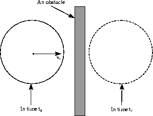
If we check the collisions by a static algorithm during this cycle we may miss a collision that has both arosen and disappeared during Dt. Although it does not lead to visible inter-penetration it may result in unrealistic behavior as illustrated in Fig. 1.
obr3.gif
Figure 1: Static collision detection lets the ball pass through the obstacle.
The solution of this problem is called a dynamic collision detection: it answers whether any two triangles have intersected during time interval át0, t1ñ and if yes then it gives the exact time tc Î át0, t1ñ of contact. More precisely, time interval át0, tcñ is collision-free but the objects are colliding in time tc + et, where et is a given precision. We see that the rest of the simulation in (tc, t1ñ must be discarded because the system is in incorrect state - the non-penetration constraint has been violated.
We will divide the dynamic collision detection algorithm into two parts:
  1. test if the objects collided and if yes then return any time te during the first collision. (There could have been more collisions during Dt, but the others are of no concern to us.)

  2. t0 and te are given such that there is no collision in t0 but there is a collision in te. Find the exact time of contact tc Î át0, teñ.

The first point is complex in general. We will show a simple solution in section 3.2. Although it is only an approximation to exact dynamic collision detection, we believe it is quite acceptable for virtual reality applications.
The second point is much easier; it can be quickly solved with arbitrary precision as described in section 3.3.

3.1  Upper Bound of Velocity

Our idea is to avoid large inter-penetration. The inter-penetration magnitude is connected to the velocity of the colliding objects. Therefore we will need an upper bound for the maximal velocity on the surface of a triangular mesh.
Lemma: Let 0, 1, 2 be vertices of a triangle T and rc0, rc1, rc2 their world space coordinates relative to the center of mass. Assume T rotates around a fixed axis with angular velocity w and translates with linear velocity v. If rcp is any point of the triangle with velocity vp then
||vp|| £ ||v|| +
max
i=0,1,2 
||w×rci ||
Proof: From equation 6 and triangle inequality we have
||vp|| = ||v + w×rcp|| £ ||v|| + || w×rcp ||
It remains to show that
|| w×rcp || £
max
i=0,1,2 
||w×rci ||
Since rcp is a point of the triangle we can write it as a convex combination of vertices
rcp = rc0 s + rc1 t + rc2 u
where s, t, u ³ 0 and s + t + u = 1. Then by the cross product distributivity, triangle inequality and a trivial property of convex combination
|| w×rcp ||
=
|| (w×rc0)s + (w×rc1)t+ (w×rc2)u ||
£
|| w×rc0 ||s + || w×rc1 ||t + || w×rc2 ||u
£

max
i=0,1,2 
||w×rci ||
[¯]
Corollary: When looking for an upper bound of a maximal velocity of any point in the triangle mesh it is sufficient to maximize velocities in the vertices.
We did not make any assumptions about the actual object orientation and therefore the upper bound is correct for arbitrary simulation time. Note that for minimal velocity of a point of a triangle this lemma does not hold - minimum may not be in a vertex.

3.2  Collision Search Algorithm

The input data are two objects A and B with shapes defined by triangular meshes, each having a bounding volumes hierarchy. The linear and angular velocities vA, wA,vB, wB of both rigid bodies are assumed to be constant during the simulation period át0, t1ñ. Using the results of section 3.1 we determine the upper bound of maximal velocities vmaxA, vmaxB of any point on object A, resp. B.
As mentioned earlier we confine ourselves to only an approximate solution. The idea of our algorithm is very simple: we perform the simulation during át0, t1 ñ with small enough steps Dt and check for collisions statically6. We stop as soon as we encounter a collision and return this time as te. It means that we really may miss some instant of collision, but we can ensure it will not be a big one - just a touch. Since no point on the surface of A (resp. B) moves faster than vmaxA (resp. vmaxB), the maximal possible inter-penetration will not be greater than
(vmaxA + vmaxB) Dt
(16)
If we can admit the maximal inter-penetration depth e then it is sufficient to take
Dt £  e

vmaxA + vmaxB
7
(17)
The e should be less than the thickness of the thinnest simulated object. For example for an application presenting a house interior, e = 1mm will lead to quite precise dynamic collision detection. Nonetheless, the smaller the e, the slower the algorithm will be in the worst case, since the number of steps is
 t1 - t0

e
(vmaxA + vmaxB)
(18)
We can improve it by introducing dynamic bounding volumes.
The dynamic bounding volumes differ from the static ones. Not by its geometry, it is the same (Sphere, AABB, OBB, k-DOP), but they bound all the rigid body positions over a time interval áti, tj ñ. Let us denote the rigid body by R (standing for either A or B) and its volume occupied in time t as Rt Í R3. Then the dynamic bounding volume V of rigid body R for time period áti, tj ñ must satisfy
V Ê
È
t Î áti, tj ñ 
Rt
(19)
Computation of such a bounding volume is simple for purely linear movement. In this case Èt Î áti, tj ñ Rt is subset of a convex hull of Rti ÈRtj, thus any ordinary convex bounding volume of both Rti and Rtj can do it.
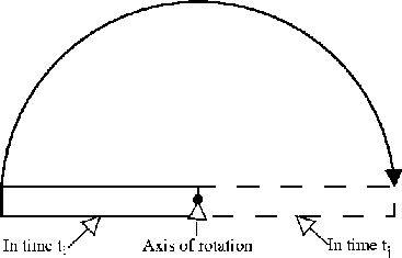
The situation for the angular motion is somewhat more complicated as illustrated in Fig. 2.
obr1.gif
Figure 2: Bounding volume of a rotated box
We define the radius Rr of object R as the distance to the most distant vertex from the center of mass. Then any rotation of the rigid body R around its center of mass will be bound by a sphere S(R) with center in the center of mass and radius Rr. Then we can use the previous result for purely linear velocity and bound the volume S(Rti) ÈS(Rtj) by any convex bounding volume.
The sphere boundary is effective only for spherical objects with the center of mass near the center of volume. For objects like the box in Fig. 2, better dynamic bounding volume should be designed, especially when considering the small angle of rotation during time interval áti, tj ñ. Such dynamic bounding volumes are object of further research.

3.3  Time of Contact

As described in section 3.2 we have found the first time of collision te and we have the time t0 without collisions as well. Then it is easy to determine the time of contact tc Î át0, teñ by the binary search. It will find tc up to a given time precision et8. The algorithm proceeds in iteration
  1. ts = t0; tk = te

  2. if tk - ts < et then return ts

  3. tm = [(ts + tk)/2]

  4. if there is a collision in time tm then tk = tm

  5. else ts = tm

  6. go to step 2

The correctness of the algorithm is obvious from the invariant: ts is always collision-free and in tk is always present a collision. The time complexity is
O æ
è
log  te - t0

et
  ö
ø
(20)
Note that the algorithm always returns the time without a collision, when the system is in a correct state.

4  Collision Response

Assume that the algorithms presented in section 3 reported a collision between rigid bodies A and B and computed the exact time of the first contact tc. Now we shall examine the collision event and methods for its handling as described in [4]. Let rA(tc), resp. rB(tc) be the point of contact of body A, resp. B in world space with respect to the center of mass of A, resp. B. The points rA(tc) and rB(tc) coincide in the absolute coordinate system (not relative to the center of mass), but their velocities [r\dot]A(tc), resp. [r\dot]B(tc) can be quite different. If the rigid body A is moving with linear velocity vA and angular velocity wA in time tc, and analogously for B, then by equation 6 we have following relations
×
r
 

A 
(tc) = vA(tc) + wA(tc) ×rA(tc)
(21)
×
r
 

B 
(tc) = vB(tc) + wB(tc) ×rB(tc)
(22)
for the actual velocities of the contact points.
The direction of the collision is described by the unit normal vector nB(tc) of the surface of rigid body B9 in point rB(tc). Important fact is that nB(tc) points out of the object B's volume. The normal direction depends on the type of contact. There are only two non-singular contact possibilities: vertex-face and edge-edge contact. For vertex-face nB(tc) is simply the normal of the face and for edge-edge contact it is the unitized cross-product of the edge directions.
Now we can examine the relative velocity vrel of the two bodies projected to nB(tc) direction
vrel = nB(tc) ·(
×
r
 

A 
(tc) -
×
r
 

B 
(tc))
(23)
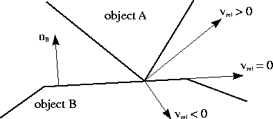
obr2.gif
Figure 3: Possible relative velocities of two objects
If vrel is positive (see Fig. 3), then the bodies are moving apart. If we have correctly computed the contact point then this option is theoretically impossible. If vrel is negative, then the bodies are approaching and if we do not change the object velocities immediately, then an inter-penetration occurs. This option is known as colliding contact and a method for computing new velocities is presented in section 4.1. If vrel is zero, the bodies are neither receding, nor approaching. This situation is called a resting contact which will be discussed in section 4.2.
Consider that we always work up to a certain numeric precision, thus we can not test if vrel = 0, since it will practically never be true. This must be replaced with something like |vrel| £ er. It follows that what we classify as a resting contact, can be a small retreating or colliding contact in reality, which introduces certain difficulties, see 4.2. However the colliding contact event is quite clear since the condition is vrel < -er.

4.1  Colliding Contact

The physical model for a colliding contact response is an impulse J, see section 2.1. The impulse direction is given by nB(tc) and what remains to compute is the impulse magnitude j (a scalar) so that
J = j nB(tc)
(24)
Once we have computed J, it is easy to compute the change of linear and angular moment (section 2.1). Recall that we use normal nB(tc) outgoing from the rigid body B, pointing towards the rigid body A. Therefore the impulse acts positively on the rigid body A and a negative impulse -J must be applied to B due to the laws of conservation. Then from the new moments we obtain the new linear and angular velocities by inverting equations 7 and 8 as explained in the end of section 2.
In order to compute the impulse magnitude j we denote the pre-impulse quantities by superscript - and the post-impulse one's by +. The empirical law for frictionless collisions states
vrel+ = - C vrel-
(25)
where C is a restitution coefficient satisfying C Î á0, 1 ñ. It is connected with the elasticity of the collision: C = 1 means perfectly bouncy collision, where no kinetic energy is lost. On the other hand C = 0 means no bounce at all, the maximum of the kinetic energy is used for example on the deformation of the objects.
The post-impulse velocities are connected with the pre-impulse one's by equations
vA+(tc) = vA-(tc) +  j nB(tc)

mA
(26)

wA+(tc) = wA-(tc) + IA-1(tc)(rA(tc) ×j nB(tc))
(27)
where mA is the mass of the object A and IA is its inertia tensor. Recall that IA depends on the rotation of the object (eq. 5) and therefore on the time tc. In the following we omit the time variable since it is always tc.
Plugging equations 26 and 27 into 21 for post- and pre-impulse velocities we obtain
×
r
 
+
A 
=
vA+ + wA+ ×rA
=
vA- +  j nB

mA
+ (wA- + IA-1(rA ×j nB))×rA
=
×
r
 
-
A 
+ j æ
è
 nB

mA
+ (IA-1(rA ×nB))×rA ö
ø
The same can be derived for B considering that B is object of opposite impulse, i.e. of magnitude -j
×
r
 
+
B 
=
×
r
 
-
B 
- j æ
è
 nB

mB
+ (IB-1(rB ×nB))×rB ö
ø
Substituting these formulas into the vrel+ expression according to equation 23 and using the unit length of vector nB, nB ·nB = 1 we have
vrel+
=
nB ·(
×
r
 
+
A 
-
×
r
 
+
B 
)
=
nB ·(
×
r
 
-
A 
-
×
r
 
-
B 
) + j(  1

mA
+  1

mB
+
nB ·(IA-1(rA ×nB))×rA) +
nB ·(IB-1(rB ×nB))×rB))
=
vrel- + j(  1

mA
+  1

mB
+
nB ·(IA-1(rA ×nB))×rA) +
nB ·(IB-1(rB ×nB))×rB))
If we apply the restitution law (eq. 25), we obtain
(-1-C) vrel-
=
j(  1

mA
+  1

mB
+
(28)
nB ·(IA-1(rA ×nB))×rA) +
nB ·(IB-1(rB ×nB))×rB))
from which we can already derive the impulse magnitude j since all the other variables are known. The inertia tensor inversion can be efficiently computed if we use eq. 5 and realize that
I-1 = (R J RT)-1 = R J-1 RT
(29)
and J-1 can be computed off-line. Moreover, the non-inverted inertia tensor will not be needed anywhere in the simulation as well as the non-inverted mass. It allows tricky treatment of objects that should not be moved at all (e.g. walls). If we pose m-1 = 0 and I-1 a zero matrix then it corresponds to objects with an infinite mass. Due to equations 26 and 27 the velocities of these objects will not be changed.

4.2  Resting Contact

As mentioned above, resting contact is a situation where the relative velocity of two bodies is negligible, i.e. |vrel| £ er. Physically based treatment of resting contact is quite difficult: [4] shows a method for the inner forces10 computation based on the quadratic programming. Another solution is based on the linear complementarity problem [2,5]. We will considerably simplify this task by not considering the friction and by assumption of only two convex objects11. These presumptions enable an intuitive geometric solution based on the idea of pushing the rigid bodies apart.
Recall that in time tc the objects are very close, but still not colliding. Because of the convexity assumption, we can use a separation theorem from computational geometry. It claims that if two convex sets are disjoint, then there exists a separation plane [12]. The problem is how to find the separation plane. To do this in a mathematically correct way we would need the nearest points from both bodies and construct the separation plane as in the proof of the theorem (see for example [12]). But since the algorithm of this section is rather heuristic, it is sufficient to approximate the separating plane, exploiting the fact that the objects are very close to each other.
We have already computed the normal nB(tc) of body B in point rB(tc). Assume for a while that the point rA(tc) is equal to rB(tc) in absolute coordinate system. Then, since the (non-strict) separating plane exists, it must pass through the point rB(tc). Because it must separate the bodies, the only choice in general is the tangential plane in point rB(tc), i.e. with normal nB(tc). This is a good approximation since the points rA(tc) and rB(tc) can be made arbitrarily close by the algorithm in section 3.3. However, the purists can always compute the two nearest points to obtain the accurate separating plane.
The idea of our resting contact solution is simple: we let the bodies move as if they were not influenced by each other (this is accomplished by the previously mentioned black box) - using the zero friction assumption. A problem may occur when the actual vrel is small but negative. In this case the objects may even collide, which is tested dynamically as described in section 3. Small inter-penetration can be prevented by process we call separation: pushing the rigid bodies apart in the direction of the normal of the separation plane. Remember that we need to simulate the time period of length Dt. It would be nice to say that from |vrel| £ er follows that the inter-penetration is small, less or equal than er Dt. Unfortunately, this is not true, because the point of contact can move to a position with higher relative velocity than vrel. This change may be arbitrarily high, since the tangential relative velocity does not need to be small. Therefore we propose an algorithm of successive separation. Supposing we simulate time period át0, t1 ñ, it works as follows.
  1. ts = t0

  2. use the black box to simulate the system during áts, t1 ñ with dynamic collision detection

  3. if collision reported in time tc Î áts, t1 ñ then stop the simulation in time tc, separate the objects to distance D and tell the black-box the new positions after separation.

  4. else return

  5. ts = tc + f(D)

  6. if ts ³ t1 then return

  7. go to step 2

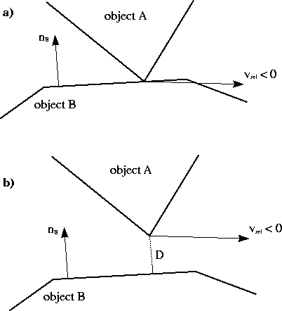
Two things remain to clarify. Firstly, the separation to the distance D means to translate the object A by vector [(mB)/(mA + mB)] D nB(tc) and the object B by - [(mA)/(mA + mB)] D nB(tc), see Fig. 4. The rigid bodies masses mA and mB are used to distribute the translation in an intuitive way.
obr4.gif
Figure 4: a) The resting contact situation, b) After separation to the distance D
How to choose the parameter D is a question of tuning. Higher D leads to faster execution, but more coarse steps. It is similar to the choice of e in section 3.2.
Another subtle point is that we must account some time for separation, otherwise the number of separations each step would not be bounded, resulting in not plausible behavior. This is expressed by function f depending on the separating distance D. A simple linear function can do this job.
Despite the simplicity of this algorithm, the separating plane idea is a basis for one of the most recent rigid body simulators [13].

5  Application

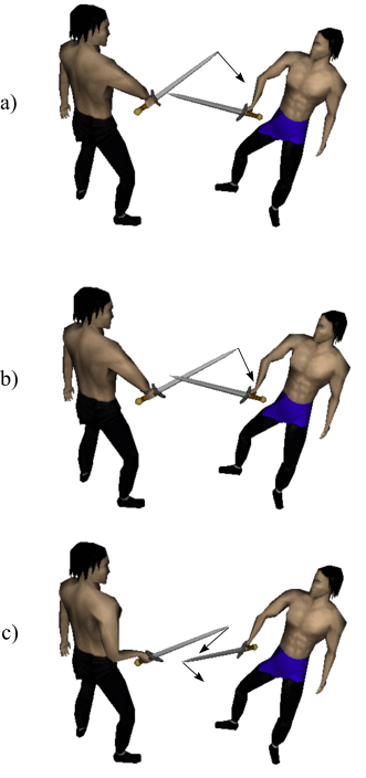
We have tested the presented algorithms in the application for virtual reality simulation of fencing. The typical collision response event in this application is illustrated in Fig. 6. In the picture the fencer on the right is holding its weapon still. The left fencer's weapon is moving with velocities depicted by arrows. The state in the time of contact, Fig. 6b, is not normally drawn in the simulation loop - it is used only for the collision response computations.
Although the weapon is drawn as a textured triangular mesh, the collision response module considers only its approximation by so called capsule. A capsule is a point set given by a line segment [`AB] and a radius r
ì
í
î
x: dist(

AB
 
, x) £ r ü
ý
þ
(30)
The point to segment distance dist can be computed quite efficiently. A capsule is similar to cylinder (both are convex), but has certain advantages.
The surface of a capsule is smooth, thus there are no problems with the definition of a normal direction nB(tc) in any point of the capsule's boundary. A test if a capsule given by [`(A0 B0)], r0 intersects another capsule given by [`(A1 B1)], r1 is simply
dist(

A0 B0
 
,

A1 B1
 
) £ r0 + r1
(31)
and the segment to segment distance can be computed also very quickly. This allows very fast collision detection, enabling small e for the dynamic collision detection algorithm presented in section 3.2.
Quite different is handling weapon to body collisions. Obviously the human body can not be considered rigid; fortunately the response to weapon-body collisions requires no dynamic simulation, since it simply means the end of the duel. Because the body undergoes many deformations resulting from motion, we use the bounding boxes re-fitting algorithm [16] generalized for k-DOPs.
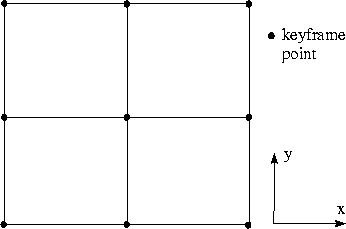
The weapon, as well as its approximation by a capsule, is controlled by some common type of input device: mouse or joystick. There is a problem that such input devices have only 2 DOF, but rigid body's position and orientation needs 6 DOF. We solved it by defining several keyframe placements of a weapon and interpolating among them according to the current state of the input device. An example of such function mapping R2 ® R6 is illustrated in Fig. 5.
obr6.gif
Figure 5: Grid of nine different key positions and orientations of the weapon in the space of an input device.
The input device controls the placement of the weapon directly and the velocities are estimated using the elapsed time Dt. This is our implementation of the black box. It remains to describe its feedback mechanism. The translation resulting from separation is straightforward. Somewhat more tricky is the reaction after colliding contact, because it is generally impossible to feed-back the movement to the input device12.
In fencing, the weapon is grasped by the fencer's hand. When the weapon is hit hardly by the opponents weapon13, the fencer looses control of his own weapon for a short amount of time (which the opponent may use to attack), because of impulse delivered by the opponents weapon. If the time of the contact is ta and the time of re-gaining the weapon control is tb (it depends on the impulse magnitude, strength of the grasp etc.), we simulate the process as follows. In time tact we compute the position and orientation P(tact) as if the weapon was not held by the hand and moving only with the post-impulse velocities computed by formulas in section 4.1. Then we interpolate P(tact) with the actual position and orientation of the hand with interpolation parameter
t =  tact - ta

tb - ta
(32)
which will give the resulting position and orientation. This simulates the process of re-gaining the control ("catching") the weapon realistically: the fencer influences its weapon movement only partially and this influence (t) increases with time.

6  Conclusions

We have presented a set of algorithms that can be used together to simulate the response after a collision of two rigid bodies. They are best suited for simple objects, such as the capsules in our application. Colliding contact is handled in a physically correct way, but the resting contact is simulated in rather intuitive way. However, the resulting post-collision motion of the objects is quite plausible as was verified in the application. We did not measure the speed of the algorithms, because it is determined mainly by the speed of the static collision test, which was not discussed. The number of iterations of the presented algorithms is heavily influenced by the e setting, as was shown in the formulas. For a majority of applications the collision response routines are not the bottleneck.
A lot of work can be done in any of the mentioned areas, mainly in the dynamic collision detection and the resting contact handling. Nonetheless, we believe that the simplicity of the referred algorithms has also its advantages, not only for the implementation's sake.

References

[1]
David Baraff. Non-penetrating rigid body simulation. Eurographics 93 State of the Art Reports, September 1993.
[2]
David Baraff. Fast contact force computation for nonpenetrating rigid bodies. SIGGRAPH, July 1994.
[3]
David Baraff. An introduction to physically based modeling: Rigid body simulation 1 - unconstrained rigid body dynamics. SIGGRAPH Course Notes, 1997.
[4]
David Baraff. An introduction to physically based modeling: Rigid body simulation 2 - nonpenetration constraints. SIGGRAPH Course Notes, 1997.
[5]
Matthias Buck and Elmar Schömer. Interactive rigid body manipulation with obstacle contacts. The Journal of Visualization and Computer Animation, 9(4):243-257, - 1998.
[6]
David Eberly. 3D game engine design: a practical approach to real-time computer graphics. Morgan Kaufmann Publishers Inc., 2000.
[7]
Jens Eckstein and Elmar Schömer. Dynamic collision detection in virtual reality applications. In V. Skala, editor, WSCG'99 Conference Proceedings, 1999.
[8]
S. Gottschalk, M. C. Lin, and D. Manocha. OBBTree: A hierarchical structure for rapid interference detection. Computer Graphics, 30(Annual Conference Series):171-180, 1996.
[9]
Chris Hecker. Physics, part 3: Collision response. Game Developers Magazine, pages 11-18, March 1997.
[10]
J. T. Klosowski, M. Held, J. S. B. Mitchell, H. Sowizral, and K. Zikan. Efficient collision detection using bounding volume hierarchies of k-DOPs. IEEE Transactions on Visualization and Computer Graphics, 4(1):21-36, 1998.
[11]
Jeff Lander. Collision response: Bouncy, trouncy, fun. Game Developers Magazine, pages 15-19, March 1999.
[12]
Jiri Matousek. Lectures on Discrete Geometry. Springer, April 2002.
[13]
Victor J. Milenkovic and Harald Schmidl. Optimization-based animation. ACM SIGGRAPH, pages 37-46, August 2001.
[14]
Brian Mirtich. Fast and accurate computation of polyhedral mass properties. Journal of Graphics Tools: JGT, 1(2):31-50, 1996.
[15]
Brian Mirtich and John F. Canny. Impulse-based simulation of rigid bodies. In Symposium on Interactive 3D Graphics, pages 181-188, 217, 1995.
[16]
Gino van den Bergen. Efficient collision detection of complex deformable models using AABB trees. Journal of Graphics Tools: JGT, 2(4):1-14, 1997.
obr5rev.gif
Figure 6: Application: Fencing in Virtual Reality. a) weapons before collision, b) state in the time of contact, c) post-collision movement

Footnotes:

1lkav8604@barbora.ms.mff.cuni.cz
2In virtual reality the positions of the objects are usually controlled directly by some kind of input device. It is more intuitive for the user than controlling the forces acting on the objects.
3In a gyroscope w(t) can change even if b(t) is constant.
4More correctly we should say that t means the total external torque as well as F is the total external force because all the contributions of individual forces and torques reflect in moments.
5There is an interesting problem connected with this step: for very precise simulation we would have to know how much time step 3 will take during its execution and add this time to Dt. Then it would be possible to draw the results in really real time. It is no problem if step 3 takes constant time but if the time depends on the state of the system (which is the case for collision response) it resembles solving a differential equation...
6This approach is sometimes called pseudo-dynamic collision detection [7].
7Obviously if the denominator vmaxA + vmaxB = 0 then there is no need for dynamic collision detection, because both upper bounds are non-negative, thus zero.
8It has nothing in common with e in section 3.2
9We could choose the body A as well, it is just a convention introduced by [4].
10 as a consequence of the Newton's law of action and reaction
11The case with more convex objects is similar to non-convex objects, since non-convex objects can be decomposed into more convex one's.
12However certain recent joysticks already support some feed-back effects.
13action known as batuta aiming to deflect the opponent's weapon


File translated from TEX by TTH, version 3.33.
On 15 Mar 2003, 18:45.