Stereoscopic face images matching
Author
Martin Klaudíny
Department of Computer Graphics and Multimedia,
Brno University of Technology,
Brno, Czech Republic
Email: mklaudiny@gmail.com
Abstract
This paper is dedicated to the problem of face images matching in passive stereoscopic photogrammetry. The aim of the presented work was to develop a method for correspondence search in a pair of high-resolution images which allows a reconstruction of high-quality 3D face model. The proposed technique combines global approach to the construction of a disparity map based on a graph cut with fast local method. The initial estimate of solution by local approach is used for reduction of a disparity space. Final disparity map is determined by single minimum cut in the reduced graph with 3D grid topology. The reconstructed 3D model of the face has good quality similar to the result by purely global approach. However, the computational time and memory consumption are significantly smaller in the proposed technique comparing to purely global approach.
Keywords
3D face capture, passive stereoscopic photogrammetry, stereoscopic matching, window-based correspondence, graph cut, maximum flow, disparity range reduction
Paper
Download the paper in PDF format here.
Further results
Additional material to the paper is presented on this website. The outputs of individual processing stages and final 3D models are displayed for the proposed technique and two reference techniques. All results were obtained under the conditions and configurations described in the paper. The images do not have original resolutions since they are adjusted for a presentation on the WWW.
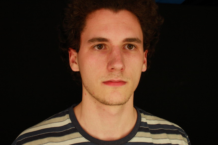
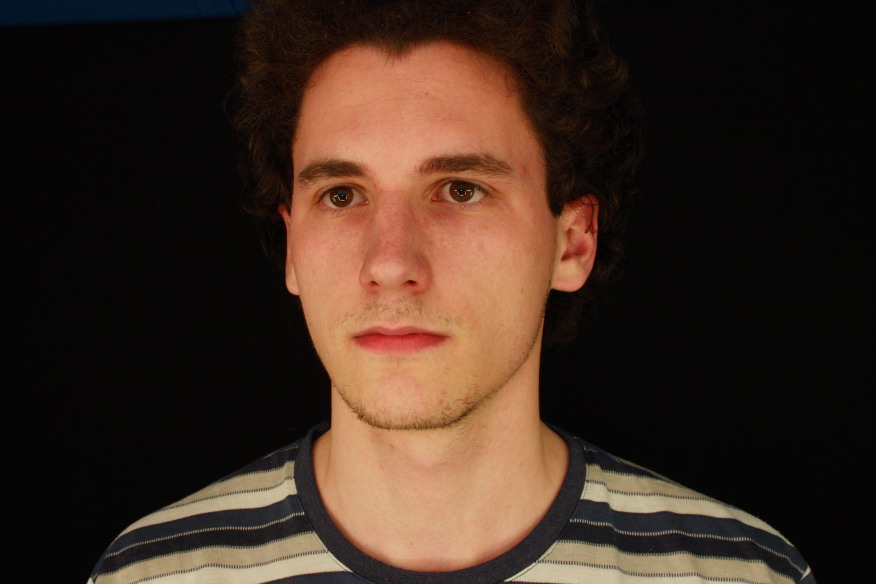
The input images of the face are shown in Figure 1. The image captured from the left is chosen as a reference image. The images do not change noticeably during the removal of lens distortion because the used digital cameras suffered from small radial and tangential lens distortion.
 (a) |
 (b) |
Figure 1: The input image from the left - reference image (a), the input image from the right - matching image (b).
|
|
|---|---|
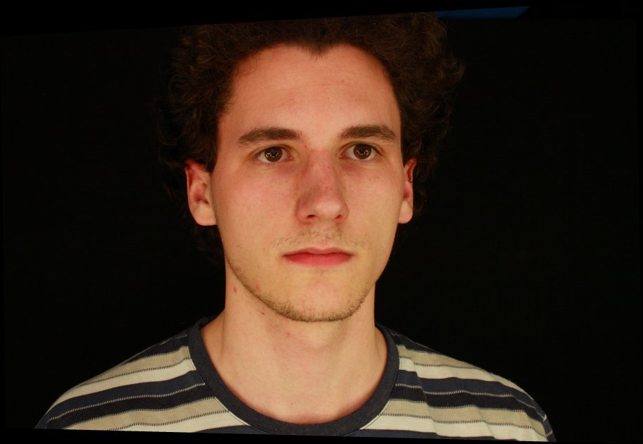
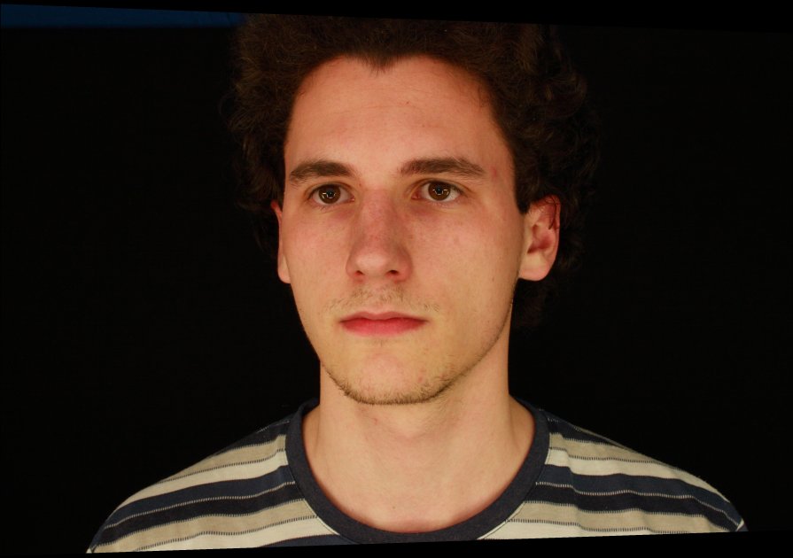
The images after the rectification are displayed in Figure 2. The correspondence search is performed on this image pair. The normalised cross-correlation calculated between the matching windows exploits only intensity values.
 (a) |
 (b) |
Figure 2: The rectified reference image (a), the rectified matching image (b).
|
|
|---|---|
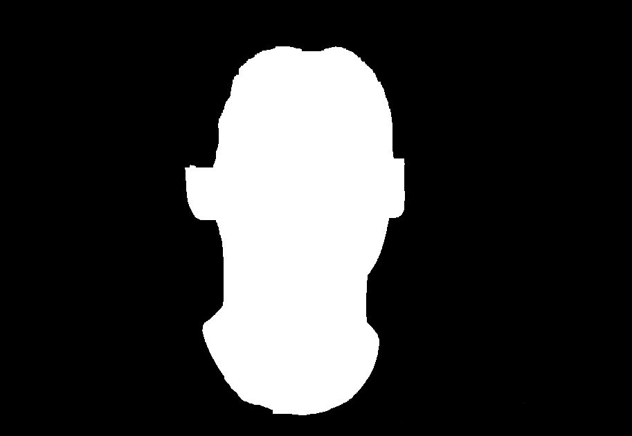
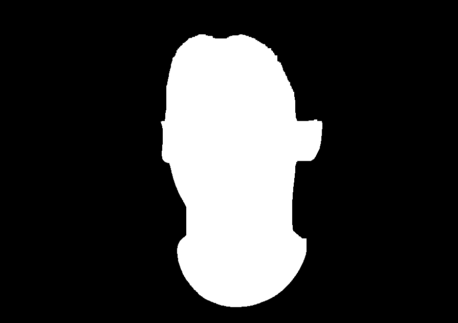
The binary masks defining face region in both rectified images are shown in Figure 3. The matching is searched only for the pixels within these regions.
 (a) |
 (b) |
Figure 3: The binary mask of face region in the reference image (a) and matching image (b).
|
|
|---|---|
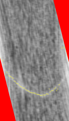
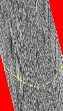
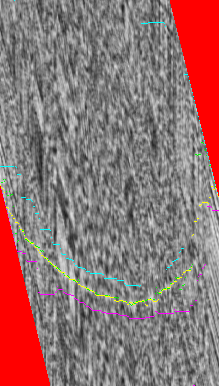
The slices through disparity space for the local approach, global approach and global approach with an estimate by local technique (proposed technique) are displayed in Figure 4. The slice is made along row in the area of forehead and only the part of slice within the face region in reference image is depicted (the row is slightly different for each technique). The axis U points in horizontal direction from left to right and the axis D in vertical direction from top to bottom. The minimal disparity value is associated with the top row of image. The values of disparity space image are rendered in grey scale whereas minimal normalised cross-correlation is mapped on black colour and maximal on white colour. Red colour marks the areas with undefined disparity space image. The size of these areas is dependent on the face region in matching image. It can be seen that the disparity space image is more rugged with decreasing size of the matching window (31x31 window in Figure 4(a), 11x11 window in Figures 4(b,c) ). The response of face within the disparity space image is visible as a bright ridge. It is less recognisable in the case of smaller window. The yellow curve represents the slice through disparity map computed by each technique. Figure 4(c) illustrates some additional information specific for the proposed technique. The green curve represents initial estimate of disparity map by local method. The minimal disparity boundary of the volume of interest is marked by cyan colour and maximal boundary by magenta colour.
 (a) |
 (b) |
 (c) |
Figure 4: The slice through disparity space for the local approach (a), global approach (b) and global approach with an estimate by local technique (c). The disparity space image together with the resulting disparity map are visualised.
|
||
|---|---|---|
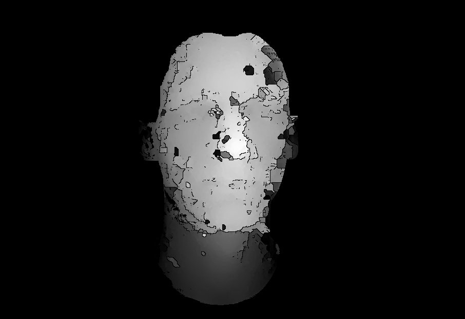
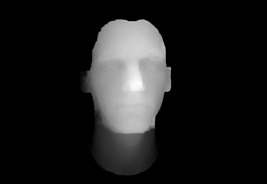
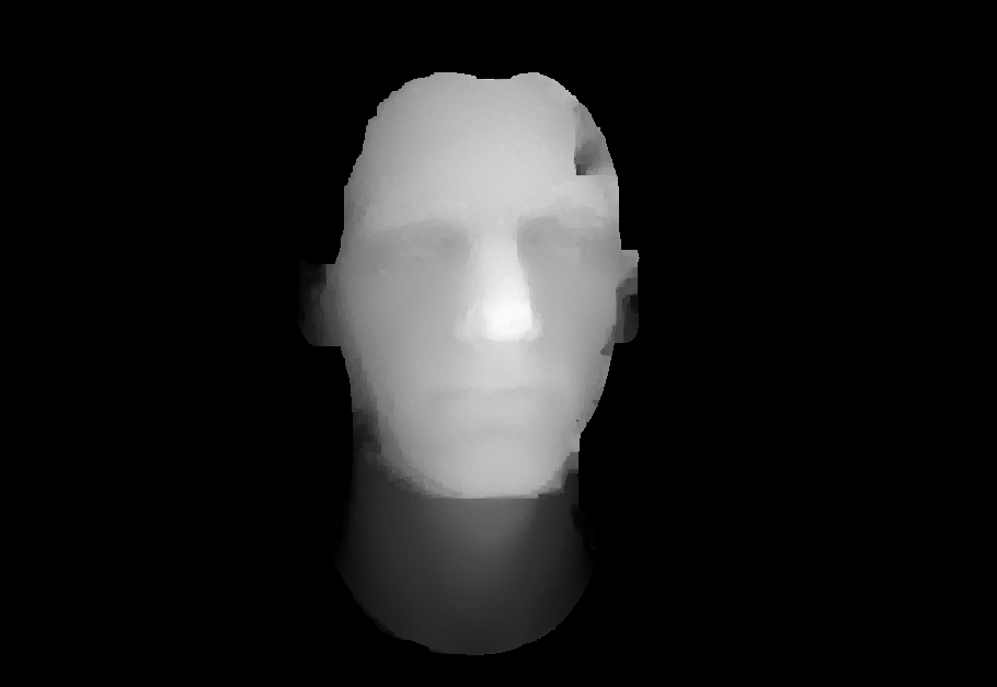
Figures 5(a, b, c) display the disparity map produced by each technique. The maximal disparity value is mapped on white colour and minimal value on black colour. Unprocessed background defined by the face region in reference image is black. The disparity map in Figure 5(a) was used as initial estimate for a computation of the disparity map by the proposed technique in Figure 5(c). Figure 5(d) shows absolute difference between the disparity map by purely global approach in Figure 5(b) and the disparity map by the proposed technique in Figure 5(c). The maximal difference (207 disparity layers) is marked by black colour and zero difference by white colour (background is black). This degradation of disparity map with respect to the purely global approach is compensated by 2.71 times quicker computation and 59.6% reduction of memory use in the proposed technique.
 (a) |
 (b) |
 (c) |
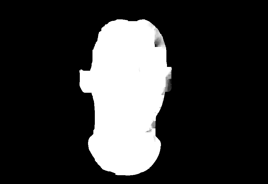 (d) |
Figure 5: The disparity map by the local approach (a), global approach (b) and global approach with an estimate by local technique (c). Absolute difference (d) between (b) and (c).
|
|
|---|---|
The reconstructed 3D model of face is represented as textured triangle mesh which has approximately 240000 triangles (slightly different number for each technique). Original VRML models are presented in a form of animation. The 3D model by each technique is visualised in two variants - shaded without texture and textured.
Local approach: shaded model, textured model
Global approach: shaded model, textured model
Global approach with an estimate by local technique (proposed technique): shaded model, textured model
Note: The videos are in AVI format and are encoded by XviD 1.0.1 codec.