Virtual Newton Telescope
Abstract
This paper presents the modelling of a Newton telescope, including its 3D representation and the simulation of its optical properties by ray tracing. The modelling of the lens system is based on Constructive Solid Geometry. The simulation also covers special optical phenomena, such as the diffraction.
Keywords:
Java, ray tracing, Monte-Carlo ray tracing, constructive solid geometry (CSG), Newton telescope, diffraction.Our objective is to create an assistant, or tool, for the construction of a Newtonian telescope, and the implementation of a ray tracing algorithm to model the light effects and optical aberrations. This tool allows us to design a certain optical configuration, as well as to verify the physical characteristics and optical properties of the specified design.
In the following sections we will present the Newton telescope, and a technique for its modelling in a world 3D. We intend to make a complete and well documented large library of 3D world primitives and ray-tracing techniques, in order to allow that these libraries serve like support teaching or to make other 3D applications. Later we will make a study of how applying different rendering techniques, like simple ray tracing and Monte-Carlo ray tracing, to simulate the optical behaviour of the telescope. As we shall see, these techniques are not sufficient for us, thus we will propose extensions to these techniques.
In order to contemplate the sky, the astronomers always used their best visual instruments: their own eyes. But, to our grief, the human eyes have some limitations, for example, the capacity to gather light. The ability to gather more light means also the ability to see farther. Galileo was the first astronomer who used an optical instrument in his observations. This instrument is the telescope, an instrument that is able to gather light that comes from distant stars.
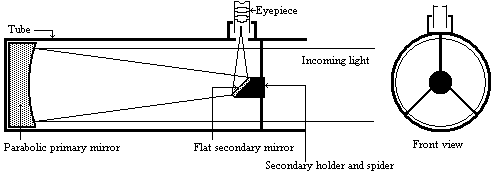
Basically, the telescopes are denominated according to their main components which have two types, the refractors (lenses) and the reflectors (mirrors). The Newtonian telescope falls into the second category, it is a reflector telescope. However, the eyepiece is composed of refracting lens.
At the time of Sir Isaac Newton (1642-1727) the only available astronomical telescopes were the Galilean refractors. This design had great chromatic aberration. Newton, not resisting to his eagerness to surpass this aberration, used a previous publication of Nicolas Zucchi who presented the concept of a free lenses telescope which was composed of only reflecting surfaces, such as mirrors. In 1672 Newton constructed the first telescope of this class using a spherical mirror, thus it had spherical aberration. In 1723 John Hadley presented a Newtonian telescope with a parabolic primary mirror, and solved the spherical aberration.

Figure 1: The Newtonian telescope
The final design is made up of a concave parabolic primary mirror and a flat secondary mirror. Since then the design has not really changed. This design, using a parabolic mirror, eliminates both the chromatic aberration and the spherical aberration, but introduces a moderate comma aberration near the field edges, and a slight astigmatism and field curvature.
Note: the diagrams are exaggerated for better interpretation.
A lens has different index of refraction for different wavelengths. This causes the light rays to pass through different focal points according to the wavelength.
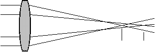
Figure 2: Chromatic aberration, the two vertical lines marks the different focal point.
The light incident at the edge of a spherical mirror is brought to a different focus from the light incident closer to the centre.

Figure 3: Spherical aberration.
This happens when we observed objects near the edge of the field. The oblique rays fail to intersect on the oblique axis. The result is called Comma. This causes that the stars that are close to the edge of field seem small comets.
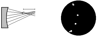
Figure 4: Comma aberration, the circle marks the best focus, and the segment shows the comet tail.
This is caused because the focal length along one diameter differs from that along another. When the object is on the axis, the two planes are identical, so there is no astigmatism. When the object is not focused, it is seen like an ellipse, no matter whether or not it is in focus.

Figure 5: Astigmatism aberration, from left to right : inside focus, best focus, outside focus.
This happens when a telescope forms an image, not on a focal plane, but on a curved focal plane. Usually it is on the edge of the field. Technically it is not an aberration, it is a feature derived from the telescope design.

Figure 6: Field curvature.
Some authors [Astro99][Oxfor97][Atmpa99] talk about other aberrations, like pincushion, distortions, focal plane tilt, etc. ..., but we are not going to consider them, because they are produced by the bad quality of the optical components, and not by the telescope design.
The quest for realism is the major goal of the rendering community, thus to achieve this goal the researchers have added physically based effects to the rendering methods, if it is possible. Particularly, the telescope introduces another physically based effect, the diffraction, which should also be simulated by rendering algorithms.
The diffraction is the slight bending of the light around the edge of an obstacle in its path [Oxfor97]. The diffraction is one of the light interference effects. Lord Rayleigh (1842-1919) was to first from those who applied the diffraction theory to the telescopes. In a Newtonian telescope the diffraction is produced by the edges of the lens or the mirror, and by the two, three or four arms that support the secondary holder. The diffraction produced by the edges of the mirror, causes that we see stars of a non-point form, but as a disc, the Airy disk [Viola99], with a series of concentric rings called diffraction rings. The Airy disk determines one of the main features of a telescope: the resolving power or resolution. The resolving power [Oxfor97] is the smallest separation between two objects which allows them just to be distinguished as separate. George Biddell Airy gave us the way to calculate the diffraction ring number zero. The Airy disk is determined by the next formula :
![]()
where Z is the angular size of the Airy disk in radians, D the diameter of the main lens or mirror and l is the wavelength.
The diffraction produced by the spider is more visible than the diffraction produced by the mirror, but is not so important (sometimes it is very nice). We can see the effects in the next image, provided by the STScI (Space Telescope Science Institute).
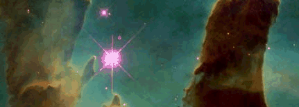
Image 1: The diffraction spikes in the Hubble telescope.
Due to its nice properties, the Newtonian design is the cheapest telescope per millimetre of aperture [Odenw97] [Lugt99], and offers the best all-round performance possible [Lugt99]. Due to this, the Newton's design has become the most popular among the amateur astronomers. Thus the final application can be useful to the community of amateur astronomers.
At the time of designing a telescope the following questions should be answered:
The answers to these questions depend on the optical behaviour of the telescope, thus they can only be given when the telescope has already been constructed. Ray-tracing methods allow us to respond to these questions. This also allows us to make adjustments to our design, without having to build the telescope.
Due to the nature of the light and the phenomena that we want to simulate, for example the chromatic aberration, ray tracing has to work separately with the different spectral components, from which the final image should be obtained [Szirma95].
If we do a preliminary study of the different rendering techniques, we can see that the visibility ray tracing is not useful to us, since rays are traced backward from the viewpoint through the pixels of the image plane assuming ideal reflection and refraction [Szirm98, Csébf97]. The colour of the appropriate pixel is computed according to the ray-object intersections. These ray tracing methods calculate the light contribution to a point, but do not calculate the diffraction light contribution.
A Monte-Carlo ray-tracing approach is path tracing [Szirm98, Csébf97]. In this ray-tracing method the rays are traced backward from the viewpoint through the pixels of the image plane, more than one times for each pixel. Then the algorithm computes the light contribution to the visible point, and from this point chooses a random direction with a subcritical probability density that is equal to the Bi-directional Reflectance Distribution Function (BRDF) multiplied by the cosine of the outgoing angle. Using this direction and the intersection point a new ray is defined and is then followed recursively. The term subscritical probability density means that it integrates to a value that is less than 1, and the “missing probability” us used to terminate the walk. This technique is called as the Russian roulette.
The colour of the appropriate pixel is computed doing the average contribution of all ray paths that have been thrown for this pixel. The contribution of a single ray-path is the radiance of the visited points multiplied by the product of the BRDFs and the cosine angles divided by the selection probabilities. If the ideal case the product of the BRDFs and the cosine angles is equal to the selection probability thus these factors compensate each other, and results in a low-variance estimator. This technique is called the importance sampling.
Aveneau and Mériaux presented a method [Avene97] to include the diffraction into a classical ray tracing. Later they improved the approach to render polygonal scenes with diffraction [Avene99], which was based on the geometrical theory of the diffraction, presented by Joseph Keller [Kelle62], using the known dihedral diffraction coefficients. First they do an approximation to the boundary edges of a polygon, using a dihedral, and then do a geometrical solution to find the diffraction path, produced by a dihedral edge, between the light source and a surface point. But they concluded that this method requires the search for comprehensive diffraction coefficients for each new shape.
Due the concept of Monte-Carlo path tracing, we can realise that including the wave nature of light in the calculus of radiance, we can reproduce the interference effect of the light. In order to incorporate the wave properties, we introduce the phase of each ray in the radiance calculation. First of all, we observe that the incoming light to our optical system comes from a very distance point. Thus we can suppose that the incoming rays have the same phase, in other words, we shall use coherence light.
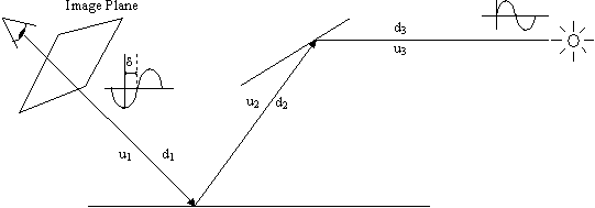
Figure 7: Path Tracing including the phase angle.
The ray will be considered as a planar wave of intensity Li and phase angle

where d i is the phase angle, uj the refraction index of the material of step j of the ray-path, dj the distance of step j of the ray-path, l the wavelength. When adding the contribution of different ray paths, we can no longer assume that the radiances can simply be added, since the ray-paths may have different phase angles. Instead, the contributions should be added as vectors. The length of these vectors is the amplitude of the wave, which is proportional to the square root of the radiance.
Finally the colour of the pixel is:

where Ix and Iy are the components for all ray contributions threw for this pixel, and N is the sample number for pixel.
In order to generate the ray-traced images, simulate the telescope and do some simulation of spatial objects (sun, planets, etc.), we need a 3D world representation. The 3D world should involve basic objects like spheres, cubes, cones, cylinders, and also composite objects built from these basic objects applying set operation. On the other hand, we also need a representation of lights, and reflective, refractive, diffuse, specular materials.
The reason of the necessity of basic objects are logical, but why we need composite objects? The first reason is that the mirror representation in a Newtonian telescope is a concave object which can simply be defined as a difference, another reason is that the lens are not simple primary objects but can also be built from these easily. One advantage is that if some day we want to model another type of telescope, then we almost surely need the same composed objects. The solution for the representation of composite objects is the Constructive Solid Geometry (CSG) [Szirm95]. This solution solves the previous problems and allows us to simulate perfect mirrors unlike a polygon-based boundary representation which does not.. Concerning the representation of the lights, we shall use point and area light sources. The reflective, refractive, diffuse and specular materials are represented by known BRDF, such as the constant diffuse BRDF and the reciprocal Phong BRDF [Szirm95]. Reflective and refractive materials are used for the mirrors and lens, and the others are for the rest of the objects, and to make a real world simulation. Finally an simplified overview of the world representation is the next one OMT (Rumbaugh’s Object Modelling Technique) diagram:
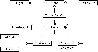
Figure 8: OMT model of the representation of our 3D world.
The CSG is a representation of solid objects. Those solid objects are composed of a set of regularised operations (Boolean operations, and the possibility of transform operations) and a set of primitives. The CSG representation is a tree where the operations are in the non-terminal nodes and the primitives are the tree leaves.
The regularised operations are functions that guarantee that the result of applying the operation on valid 3D objects is also a valid 3D object. The validity means that the object does not have lower dimensional parts. The basic regularised operations, for the CSG, are the next Boolean operations:
and then you can extend this set of operations with scaling, translation or any other geometric operation.
The primitives are classical 3D objects, including sphere, cube, paraboloid, etc. Having an overview of CSG, we can make one example of a CSG with a three simple 3D Primitives (cube, cone and sphere) and two regularised Boolean operations (U*,/*):
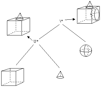
Figure 9: CSG representation of a solid object.
We have decided to implement the algorithms in Java, because of the following advantages [Frouf96]:
The really pending subject of Java is the efficiency which is about 10-20% less than of a same program written in a very efficient language like C. Despite this we have to consider that the complexity of the algorithms is the same, independently of the implementation language, thus the ”inefficiency" of Java is a multiplicative factor, which can often be discarded. We also have to mention that the new versions of Java will be more efficient (like the Java2 that uses a Just In Time compiler).
We presented the Newtonian telescope, and a technique to model it in a 3D world. Then we introduced the diffraction phenomena and proposed a method to incorporate it into the ray tracing method for its simulation. The implementation of the algorithms has already been started, and the world representation and the standard and Monte-Carlo ray-tracing parts have already been elaborated. At the moment, this is a work in progress, which aims at the addition to diffraction to the ray-tracing implementation, and the telescope generator.
Future work can add new designs of telescopes like refractor or catadioptric systems like Schmidt-Cassegrain system. Other possibilities are to improve the ray-tracing methods to simulate the atmosphere phenomena. Another really interesting feature could be the auto-generation of the stars to be rendered by the program from existing on-line star catalogues.
We would like to give our sincere gratitude to László Szirmay-Kalos for introducing the rendering. We would like to give thanks to Mateu Sbert Casasayas to make our stay possible in Budapest with a SOCRATES program, to make our final project. The project was also supported by the Spanish-Hungarian Fund ref. No. E9 and by OTKA project, ref. No. T029135.
[Astro99] AstroRed Página de recursos astronómicos. http://www.astrored.org (in spanish)
[Atmpa99] Amateur telescope making page. http://www.atmpage.com
[Avene97] Lilian Aveneau and Michel Mériaux. Phénomčnes ondulatoires en synthčses d'images. Revue internationale de CFAO et d'informatiquegraphique, 1997 ( in french ).
[Avene99] Lilian Aveneau and Michel Mériaux. The discrete tube : a spatial acceleration thecnique for efficient diffraction computation. Proceedings of DGCI'99,Noisy le Grand, March 1999.
[Csébf97] Csébfalvi Balázs A Review of Monte Carlo Ray Tracing Methods. Central European Seminar on Computer Graphics, April 1997.
[Frouf96] Agustín Froufe. Tutorial de Java http://www.dcen.uson.mx/JavaTut/index.html ( in spanish )
[Kelle62] Joseph B. Keller. Geometrical theory of diffraction. Journal of the Optical Society of America, February 1962.
[Lugt99] Marinus Lugt. The Newtonian pages. http://members.aol.com/atmlugt/
[Odenw97]Dr. Sten Odenwald. Ask the astronomer. http://image.gsfc.nasa.gov/poetry/astro/qanda.html
[Oxfor97] Ian Ridpath. Dictionary of astronomy. Oxford university press.
[Szirm95] László Szirmay-Kalos Theory of three-dimensional computer graphics Akadémiai Kiadó, Budapest, 1995
[Szirm98] László Szirmay-Kalos Stochastic Methods in Global Illumination - State of the Art Report, Technical Report, Computer Graphics Institute of the Vienna University of Technology, TR-186-2-98-23, www.cg.tuwien.ac.at, 1998
[Viola99] Francisco A. Violat Bordonau. Problemas y Ejercicios de Astronomía Planetaria Equipo Sirius 1999. ( in spanish )