3D Editor for Traffic Playground
Petr Stružka,
xstruz01@stud.fee.vutbr.cz
Department of Computer Science and Engineering
Technical University of Brno
Brno / Czech republic
Abstract
This contribution presents one
part of complex Traffic
Playground, which cover editing squares,
the base elements of the Playground. The program's output contains 3D representation
of the squares and its semantic description including description of the
traffic situation. The program that implements the project works under
Win95/NT environment and uses Direct3D (a part
of DirectX extension).
Keywords: Traffic playground,
DirectX, Direct3D, X file format, square map, square
1. Introduction
The contribution describes the
concept of the Traffic playground and it also contains some implementation
details connected with the DirectX graphics API.
1.1
The Traffic playground
The Traffic playground system
is intended as a connection of traffic rules tutorial program and for practicing
in the form of game. The Traffic playground project users will be
mainly children and is designed for children, but it can be useful for
other users, mostly for teachers in driving schools. The program allows
them to improve their knowledge of the traffic rules. Using the system,
it is possible to try basic responses to various traffic situations, that
are simulated by the system and presented to the user in a simple way.
The Traffic playground is a simulation of real situations. User
drives a simulated vehicle through the playground, which includes crosses,
curves, road signs and other elements of real traffic. The main advantage
of the system is visualization, which attracts users like a computer game
(much better then answering a test forms in driving schools). The program
is not designed for driving school lessons. The intended purpose is to
give an experience and to practice quick reactions in given situations
(minimal knowledge of the traffic rules is required).
The program Traffic playground
consist of two individual parts. The first part is a 3D view to selected
situation which can be e.g. a view from car's cab driven by the user. The
second part is the Editor for Traffic
playground. It allows creation of complete appearance of 3D scene
including 2D square placement. Users can insert road signs and place them
in the scene in an easy way, they can add new elements to the scene created
before or build the scene from scratch, it is possible to create new maps
of squares, etc. Output files (that includes semantic description of each
square) of the 3D Editor are used in the 3D viewing engine.
1.2 DirectX
The Microsoft DirectX Software Development
Kit (SDK) (for additional information see reference [2]
) provides a finely tuned set of application programming interfaces (APIs)
that provide you with the resources you need to design high-performance,
real-time applications. DirectX technology will help build the next generation
of computer games and multimedia applications.
Microsoft developed DirectX because
it wanted the performance of applications running in the Microsoft Windows
operating system to rival or exceed the performance of applications running
in the MS-DOS operating system or on game consoles.
DirectX includes several components:
DirectDraw accelerates hardware and software animation
techniques by providing direct access to bitmaps in off-screen display
memory, as well as extremely fast access to the blitting and buffer-flipping
capabilities of the hardware.
DirectSound enables hardware and software sound mixing
and playback.
DirectPlay makes connecting games over a modem link
or network easy.
Direct3D provides a high-level Retained-Mode interface
that allows applications to easily implement a complete 3D graphical system,
and a low-level Immediate-Mode interface that lets applications take complete
control over the rendering pipeline.
DirectInput provides input capabilities to your game
that are scalable to future Windows-based hardware-input APIs and drivers.
Currently the joystick, mouse, and keyboard are supported.
2. 3D Editor
2.1 General
3D Editor for the Traffic Playground
is an application running under system MS Windows 95 / MS Windows NT version
4.0 or later. During execution, the program uses DirectX, especially Direct3D
interface. It is necessary DirectX to be installed on your system, at least
version 3.0 is required. Graphics card with 3D accelerator and minimal
4MB video memory is recommended to get enough space for textures. Program
is a standard Windows application with all its features.
2.2 Editing modes
This application provides efficient
and comfortable interface for creating, editing and manipulating the Traffic
playground objects. Main object is a playground and consist from
squares. General 'road map' is composed from particular 'road maps' of
elementary squares. Powerful and easy tools have been implemented for editing
both objects. Therefore, two editing modes are defined.
First mode is two dimensional
and manipulates a map of squares. Using this mode, the user can efficiently
handle the squares and determine general 'road map' of the playground.
Creating a new playground produces a new map of NxM squares. This 2D editing
mode allows user to affiliate a specific traffic situation to each square.
It also gives the overview of whole playground and maintains the traffic
situation context.
Second mode is three dimensional
and enables editing of the elementary squares. It's possible to work with
only one square at a time in this mode, because 3D editing mode is specialized
for creating objects on square and manipulating them. The user can use
several groups of predefined objects to specify requisite features of each
square. That means user can change the traffic situation by adding or removing
traffic signs (for example road signs) or he can use an object from another
group to make the outlook of playground more realistic (for example trees).
 Figure 1: A sample of application Editor for
the Traffic playground
2.3 Structure of the
Traffic playground
Playground is designed as a workspace,
which can be displayed and includes model of some real or artificial traffic
playground.. That workspace is divided into NxM squares, which are the
basic construction blocks for the playground. Minimum size of playground
is only one square. This means that the square is an elementary unit of
the playground and can not be divided in any smaller elements. Only one
road element can be found in one square (i.e. cross, direct way, curve,
etc. - see table of squares to get more information).
The whole playground can be constructed by adding squares into the map.
The map determines position of squares in the playground. Detailed maps
and squares description is described in the next couple of paragraphs.
2.4 Traffic playground
map description
In 3D editing mode the user can see
only one square. Hence some way of maintaining the user aware of context
of constructed squares in the map is needed. It is provided by the map
of squares. The map of squares is a 2D structure which maintains square
positions and gives overview of the whole playground. The purpose of this
map is to allow user to comfortable edit the playground and to quickly
work with the squares, which have already been created. The map of the
playground is stored in text file with MHD extention. This file includes
the complete information about playground needed for its construction,
for example information about square files and positions.
2.5 Square description
Square is basic element of the Traffic
playground and can not be divided into smaller parts. The user
can use only predefined squares with specific road elements. It is not
possible to define new road elements at this time (this feature will be
added to this application in the next version). To get more information
about the square faces see table of squares.
The purpose of the Traffic
playground is to simulate real traffic situations. Tools have been
implemented for building and handling traffic signs (e.g. road signs).
The user has the possibility to choose arbitrary road sign from the given
set of signs and place it into the scene. These actions can be performed
in 3D editing mode only. The user can create and place objects on square,
manipulate the objects (change their positions), or remove these objects
from the scene. It was intended to create more realistic and humanistic
application and that is why a couple of tools creating and handling object
that appear in the nature, especially plants like trees, bushes, etc. was
added.
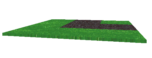
 Figure 2: A sample of a square
Square description consists of
two files. The first file stores squares in format X defined by Direct3D
interface. The X files format allows to save files of meshes, textures,
animation sets, etc. Mesh representation was chosen for saving into the
files with reference to textures required by the squares. Templates use
such format, too. The textures are shared by all the objects and they are
read from directory named TEXTURE. The X file contains complete design
of 3D scene of the square, including road signs, traffic signs and ambient
objects. All that object are stored to file as a single mesh with texture
mapping. During the saving procedure, the file is created from scene
hierarchy (as described in the above paragraph). The basic size of
the square is 500x500 points. One square can be placed onto the playground
repeatedly to avoid unnecessary creation of the squares with same content.
The next file can be text file
with extension PCT, or it can be recorded directly in file withmap of squares
(MDH file). If the square is created as a single square in the 3D
editor without other association to map of squares, the description
PCT file is generated. This file (or record, the content is the same) contains
basic information about the square. During playground editing, it is possible
to add this file (mainly its 3D presentation in X file) into given place
in new or currently edited map of squares. Then the square description
is stored into the general map description (that means to file with MDH
extension).
Square description is organized
according to the following rules. Section's name is derived from the X
file name, which is the main square identification. Basic face is determined
in variable named TYP. Value can be in range of 0-15.
It appears to all possible 'road maps' in one element. The value 0 means
green place, which is implicitly inserted in free spaces not occupied by
any square. This process does not need other special definition. Naturally,
it is possible to create and place for example forest or building, but
it does not affect the traffic situation at all. Variable named POZICE
is filled with list of all positions used in the edited map. Next variable
ZNACKY defines list of all used road signs in the square. If the list of
road signs is defined in this way, it should be defined with the same number
of variables with detached names of road signs. The value is defined by
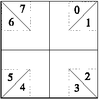
the vector(s) (q, x, y, r). Character q means one eighth of square the
road sign is placed, x,y is its position, and r is its radius.
 Figure 3: Numeric mark of each eighth
2.6 Trajectory alternatives
In the Traffic
playground, traffic is simulated, e.g. vehicles are in motion,
etc. To do the simulation, it is necessary to define how the car can move
in the playground. The car's motion should be defined so that no collision
with other objects occurs. The car should move only on the predetermined
roads and hold the traffic rules like in the real life.
If the map of squares is correctly
defined, all the roads leading from and to all squares must be connected
to the neighbour square. Maintaining this rule is enabled by only having
the trivial square types. The car trajectory is defined by road placement.


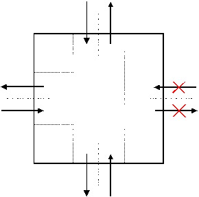
 Figure 4: A sample of part of the map of squares
includes square which is not connecting
The second problem is traffic signs,
which specifically regulate traffic on the roads. As can be seen, the car
can not pass through, if there is a road sign "entrance prohibited", etc.
But if there is no visible barrier on the road, nobody can constrain to
driver takes this course, except his own will or a policeman.
It means, that if we want to
solve the square course problem, we should speculate not only with a cross
face, but also with traffic signs which can lower a set of alternative
trajectories, too. For this case, input and output points are defined to
and from the squares. Each square could have the maximum of a four square
input or output points. The denomination of those points is in the following
figure and is similar to the square eighth marking.
In the square description variables
VJEZD and VYJEZD are defined, that cover a list of all possible entrances
and exits. The values can be 1,3,5,7 respectively 0,2,4,6. If no value
defined, or the number is not listed, the given gate passage is impossible.
The correctness of that feature is possible only on the whole playground
level.

Figure 5: Definition of the input and output
points
For easier navigation in the scene,
a semantic description of cross passage through the square is defined.
This semantic is usable mainly for other part of the Traffic playground
system, which controls cars' motion. It should be freed from analyzing
of the complete scene to get a current traffic situation to determine cars'
trajectory. Holding those techniques will accelerate execution for navigation,
which could be a part of a scene rendering program.
2.7 Files
Other
files needed the program runs are texture and object template files. Textures
are stored in TEXTURE directory which contains all textures (such as tree
texture, road signs, etc.) used in the scene. The textures are stored in
MS Windows bitmap (BMP) format. Object templates are stored in TEMPLATE
directory in X file format. The object template files contain predefined
3D objects, such as road signs, basic squares, and all 3D objects used
in the editor.
3D templates were created using
Autodesk 3D Studio editor and stored in 3DS format. Transformation to X
file format was performed by a convert utility (resulting in mesh format).
Directory HRISTE contains stored
map of squares of the Traffic playground
and related X files. It is recommended to store each playground in separate
directory. Directories that contain examples for the Traffic playground
are provided and contain files called Hriste2.mdh and kolo.mdh. For better
illustration, see the above mentioned example files or appendix.
3. Implementation
The program Editor
for Traffic playground was implemented under Microsoft Windows
95 system using Borland C++ 5.0 programming language. For 3D graphics drawing,
Retained-Mode Direct3D interface was used. The program allows for editing
one square at one time. Object oriented principles were used in the implementation.
Every window or dialog uses its own class. Control over Direct3D
and basic objects, e.g. a complete scene and its frame object hierarchy,
is implemented in class TDirect3DCtrl. This class contains data structure
of the Traffic playground.
3.1 Direct3D initialization
Direct3D and DirectDraw interface
functions are imported directly from system libraries. This is done using
definition file of the project with IMPORTS keyword, which is followed
by the name of a library and imported function:
IMPORTS D3DRM.Direct3DRMCreate
IMPORTS DDRAW.DirectDrawCreateClipper
.
.
etc.
The main initialization of Direct3D
interface is done by Direct3DRMCreate function, which results in pointer
to the selected structure. In next step, it is necessary to call DirectDrawCreateClipper
function, which ensures graphics cropping to selected window. This step
is followed by parameter setting, such as model etc. Calling TDirect3Dctrl
class method CreateDevice3D sets up device and retrieves color depth, that
is needed for setting different color and texture quality level. Some of
these parameters can be changed while the program runs.
3.2 Internal
data structures
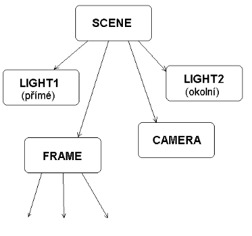
Objects in the scene are ordered
in a frame hierarchy -- they are connected in a tree structure. Other objects,
such as lights, camera (means viewing point), and others are connected
to the root frame. The above described hierarchy is implemented
in AppInfo structure that contains the basic references to the scene (scene
type is frame too, and it is the root of the hierarchy tree), camera,
device and rendering mode in the class TDirect3DCtrl. This structure is
well suitable for object manipulation, where it must be possible that changes
done to parents apply to all their children. The basic structure of the
hierarchy tree is displayed in followed figure.
 Figure 6: The scene object hierarchy
The map of squares is represented
by ActHriste structure. It includes aktivni variable, which
distinguished the method of editing of the square. If the map of squares
is loaded, the variable is set and currently edited square is part of opened
playground and has own position (which can be multiple); all other information
about square is stored to the map of squares of playground. Otherwise this
information is stored in separate file with PCT extension. Other variables
describe map file name, x and y size, number of non zero squares (X file
must exist for each non zero squares), and list of X files,
Another variables are template_path
and texture_path, that contain paths to templates and textures.
It is assumed that this directories are placed to the directory containing
main program. These paths are used for inserting objects to scene and calling
the texture load function.
The variables idTimer; fpsTimer
and hwndTimer; are used to screening timing setup. Variable idTimer
is unique timer identifier, variable fpsTimer determines the number
of frames displayed per second, and hwndTimer is handle to the timed
window.
4. Direct
3D
Direct3D provides the API services
and device independence required by developers, delivers a common driver
model for hardware vendors, enables turnkey 3D solutions to be offered
by personal-computer manufacturers, and makes it easy for end-users to
add high-end 3D to their systems. Because the system requires little memory,
it runs well on most of the installed base of computer systems.
Direct3D is implemented in two
distinctly different modes: Retained Mode, a high-level API in which the
application retains the graphics data, and Immediate Mode, a low-level
API in which the application explicitly streams the data out to an execute
buffer. Direct3D Retained Mode API is designed for manipulating 3D objects
and managing 3D scenes. Direct3D Immediate Mode is Microsoft's low-level
3D API. It allows you to port games and other high-performance multimedia
applications to the Windows operating system.
The Direct3D API (like the rest
of the DirectX API) is built on top of a hardware-abstraction layer (HAL),
which insulates you from device-specific dependencies present in the hardware.
A companion piece to the Direct3D HAL is the hardware-emulation layer (HEL).
The Direct3D HEL provides software-based emulation of features that are
not present in hardware. For more information see [2].
5. Conclusions
The purpose of this project was
to design and implement Editor for Traffic playground
program, that is part of the Traffic
playground system. This application is especially designed so that
it can use DirectX graphics interface. The project
also involved semantics of car navigation through the crossings and verification
of the road map consistency.
The future work (on next version
of this application) will include solving problems of global definition
of the square descriptions and also more general description of squares.
It would be also useful to create
better inner structure in file storage of the scene description. Such structure
can benefit from better X file and memory structure understanding achieved
during this project. The next version of the Editor for Traffic playground
will integrated broader palette of basic elements and also other elements
that will improve appearance of the scenes.
6. References
[1] Thompson, N: 3D Graphics Programming for Windows
95, Microsoft Press, USA, 1996
[2] Microsoft DirectX 3
Software Development Kit, Microsoft, USA, 1996
(URL http://www.microsoft.com/directx)
[3] Fořt, I: Windows - Techniky programování
(in Czech), Grada, Praha, Czech Republic, 1993
7. Appendix
7.1 Tables
|
DESCRIPTION
|
SQUARE TYPE
|
IMAGE
|
|
Free Place
|
0
|

|
|
Start, direction Z+
|
1
|

|
|
Start, direction X+
|
2
|

|
|
Curve
|
3
|

|
|
Start, direction Z-
|
4
|

|
|
Direct way, direction Z
|
5
|

|
|
Curve
|
6
|

|
|
Cross T
|
7
|

|
|
Start, direction X-
|
8
|

|
|
Curve
|
9
|

|
|
Direct way, direction Z
|
10
|

|
|
Cross T
|
11
|

|
|
Curve
|
12
|

|
|
Cross T
|
13
|

|
|
Cross T
|
14
|

|
|
Cross
|
15
|

|
Table 1: Square faces scheme
7.2 Examples
The following text is an example
of the map description. The text contains information about the map size,
positions of squares, and traffic signs (see Chapter
2).
file KOLO.MDH:
[Mapa dopravniho
hriste]
;this file was created
by 3D editor and be sure exist files .x
Magic=2
Kompletni=1
Verze=1.0
Rozmer=2x2
Pocet ctvercu=4
Soubory=k1.x,k2.x,k3.x,k4.x
Start=1:0,+z
[k1.x]
typ=6
pozice=0:1
Znacky=A1A,A1B
A1A={1,430,420,0)
A1B={7,420,430,180)
Vjezd= 1,7
Vyjezd= 0,2
[k2.x]
typ=12
pozice=1:1
Znacky= A1A,A1B
A1A={1,430,420,0)
A1B={7,420,430,180)
Vjezd= 1,3
Vyjezd= 2,4
[k3.x]
typ=3
pozice=0:0
Znacky= A1A,A1B
A1A={1,430,420,0)
A1B={7,420,430,180)
Vjezd= 1,5
Vyjezd= 4,6
[k4.x]
typ=9
pozice=1:0
Znacky= A1A,A1B
A1A={1,430,420,0)
A1B={7,420,430,180)
Vjezd= 3,5
Vyjezd= 0,6


