
Figure 1a) Input Figure 1b) Output
Abstract1. Introduction
2. The algorithm
2.1. Determination of the basic geometric buffer
2.1.1. Determination of the left and right line segments
2.1.2. Determination of semicircles
2.1.3. Determination of the banding rectangle
2.2. Finding the intersection points between BGB
2.2.1. Intersection of two line segment
2.2.2. An intersection of line segment and a semicircle
2.2.3. Intersections between semicircles
2.2.4. Elimination of covered intersection points
2.3. Construction of the common outline
2.3.1. Determine the direction of movement
2.3.2. Performing the walk-about
3. Conclusion
The paper considers the problem of polylines outline
construction. The algorithm works in three steps. At first, so called basic
geometric buffers (BGB) are determined. Then, the intersection points between
them are calculated. The intersection points are checked for containment
in existed BGB. Only those intersection points not covered by any other
BGB are used in the third part of the algorithm when the walk-about through
the intersection points determines the final polylines outline.
The problem of generation of an outline can be found in different applications. O'Rourke studied it as the key to safe robot arm movement [O'ROU93]. However, this problem is also of great importance in GIS applications. Let us consider a high-way (by the way, the high-way is in general represented by two parallel polylines) and let us suppose, we are interested in the area of propagation depending the terrain configuration. This information serves then to the road planner to decide where the noise barriers are needed.
The solution to this problem is quite simple at
the first sight. Let us suppose we have a disk with a variable radius and
we are moving the disk's centre point along the input polyline. The points
of the moving disk arm the outline of the polyline. Theoretically the solution
is obtained simply by the Minkowski sum (see [O'ROU93]),
but practical implementation is not so simple. In this paper, the first
prototype algorithmic solution to this problems is given.
The program input is a set of polylines (Figure 1a). Each polyline consist of several line segments, and two distances (di,1 is on the left side and d i,2 on the right side) are associated with each line segment li (see Figure 1a). The algorithm then calculates the outline as shown in Figure 1b.

Figure 1a) Input
Figure 1b) Output
The algorithm works in three steps:
2.1. Determination of the basic geometric buffer
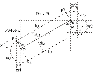
Each BGB has the same structure: it consists of
two parallel line segments (li,1, l i,2) on the left
and right side of the input line segment li and two semicircles
(ci,1, ci,2) which connect these two line segments
(see Figure 2).

Figure 2 BGB
The BGB is determined in three steps:
2.1.1.
Determination of the left and right line segments
This problem can be solved in two ways:
1. The first solution uses geometric transformations (translation and rotation) and it is easy to implement by the following steps:


Figure 3a) Original position
Figure 3b) Moved position
Figure 3c) Rotated position
The following operations are needed for obtaining this solution:

2.1.2.
Determination of semicircles
To determine the semicircle data, the radius, two center points and two initial angles are needed (see Figure 2). Radius and center points are easy to be determined (see Equation 8 and Equation 9).
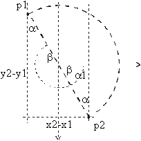
A bit more care should be given to determining of the initial angles a1 and a2. In fact, it is enough to calculate only one angle. The other one is obtained by adding 180° to the calculated angle.
By the help of the line segment connecting the beginning and the end of the semicircle (see Figure 2) the initial angle is calculated(see Figure 6 and Equation 10):
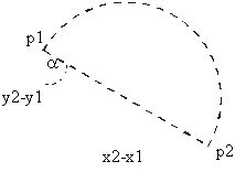
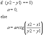
Figure 6 How to get angle a
Equation 10
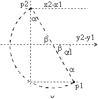
There exist two possibilities to calculate initial angles a1 and a2 (see Figure 2):
The algorithm does not determine the smallest banding rectangle because its determination would take a lot of time. In that case, we would need trigonometric operations, multiplications, square root operations, division, additions and subtractions. So we use a method where we needed only 2 additions and 2 subtractions (see Figure 2), but the banding rectangle is a bit larger than necessary.
At first, the minimum and maximum value of co-ordinates p1, p2, p3, p4 in each co-ordinate direction are determined. (minX, minY, maxX, maxY)
Then the banding rectangle is stretched for the value of semicircle radius in each direction (see Figure 2 and Equation 13)
2.2. Finding the intersection points between BGB
To reduce the number of calculations, the banding rectangles are used. If two banding rectangles overlap, it is possible that intersection points exist and the future actions are necessary.
In Figure 9, we can see all possible intersections that can occur:
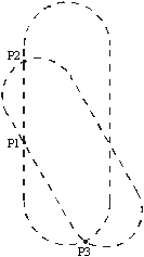
Let us consider these cases briefly.
2.2.1. Intersection of two line segment
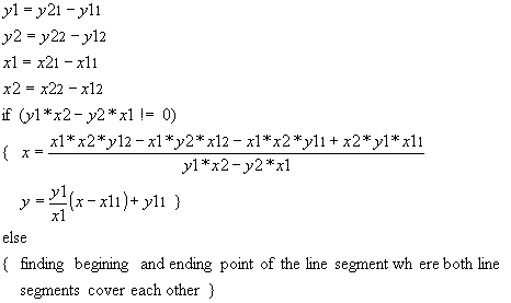
The input data consists of beginning and ending
points of two line segments (line segment1 [(x11,y11),
(x21,y21)]; line segment2 [(x12,y12),
(x22,y22)]).
This case is simple enough that it does not need
additional observation. For the purpose of completeness let us give just
the final formula (see Equation 14)
2.2.2. An intersection of line segment and a semicircle
The input data consists of beginning and ending points of a line segment [(x11, y11), (x21, y21)], and data describing a semicircle (center point (xs, ys), radius (r) and initial angle (a )). There are three possible solutions (see Figure 10):
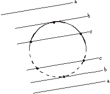
Basic formulae are described in Equation 15.
If x21 = x11 then the Equation 16 is obtained.
In other case, the Equation 17 is applied.
These equations actually consider the intersection
between a line and a circle. Therefore, it has to be checked if the intersection
points lay on the line segment and the semicircle indeed.
2.2.3. Intersections between semicircles
At first, the intersection points between two
circles determined by center points [(xs1, xs1), (xs2, ys2)], radii (r1,
r2) and initial angles (a 1, a
2) are determined.
The circles are expressed by formulae in Equation
18.
First, the distance (d) between center points and absolute difference (drad) between radii are calculated (see Equation 19).
With these two parameters, the following cases should be considered:
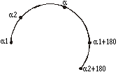
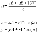


Figure 13a One circle is inside the other
Figure 13b Circles have no common surface
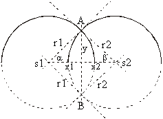
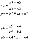
At the end, it has to be checked if the intersection
point (or points) lies on both semicircles.
2.2.4. Elimination of covered intersection points
After obtaining the intersection points, we have to remove those which are inside any BGB. Let us see the example in Figure 16.
The final outline goes through intersection points
q1, q2, q3, q6, q7, q1.
Points q5 and q4, which are covered with BGB
are not a part of the solution, so we delete them (see Figure
16).
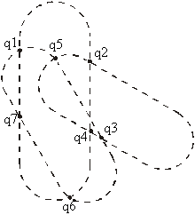
Figure 16 Found intersection points
This problem is naturally separated into two smaller problems:
2.3.
Construction of the common outline
When all necessary data are obtained the common outline is obtained. It consists of exactly one outer border (named loop) and zero or finite number of inner borders (named rings) [MORT85]. The rings represent the holes in the outline.
If there exist non-covered intersection points, we continue with the following:
2.3.1.
Determine the direction of movement
In our case, the clock-wise direction of movement is chosen. At the first point the right direction has to be calculated.
The direction is determined by the vector product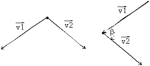
Figure 17 Direction of next movement
Because we travel in the clockwise direction,
we always follow the vector which lies in the left halfplane of the other
vector (see Figure 17). With other words, if the
vector product is positive the first vector (v1) is followed and if it
is negative the direction of the second vector (v2) is applied.
2.3.2. Performing the walk-about
The walk-about is relatively easy to implement:
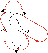
The walk-about starts at point q1. By the help
of the vector product, the direction of vector v is chosen. The next intersection
point is q2. Here we jump on the second BGB and follow its outline until
intersection point q3 is found. Here again the BGB is changed. The process
continues until q1 is meet again.
The paper considers an outline construction algorithm. The most difficult task of the algorithm considering spent CPU time is the elimination of found intersection points covered by BGBs. At this moment, we do not use any acceleration techniques (plane subdivision). However, the described algorithm is being used successfully at the Faculty of Civil Engineering for the road design. The implementation turns out as being stable and quick enough for their purposes. The algorithm has been implemented in C++ and can be found at http://www.uni-mb.si.
[MORT85] Mortenson, M.E., ''Geometric Modelling'', John Wiley & Sohns, 1985.
[O'ROU93] O'Rourke, J., ''Computational Geometry in C'', Cambridge University Press, 1993