FIG. 1. DDA Algorithm
Vladimíra Dudíková, Zuzana Černeková, Milan Prochaczka, Silvester Czanner
{dudikova | cernekova | prochaczka}@st.fmph.uniba.sk
Department of Computer Graphics and Image Processing
Faculty of Mathematics and Physics
Comenius University
Bratislava
In this article we present some methods of the algorithm animation. The whole project has educational character. The goal of the whole work is to create a video and a shipping document. This will illustrate some graphics algorithms `in action'. The viewer should be able to implement the presented algorithm after watching the film. A tape will be used in praxis.
Keywords: computer graphics, animation techniques, graphics algorithms
This paper gives some small description of the animation of the computer graphics algorithms. The goal of whole work is to create a video and shipping document. This will illustrate some graphics algorithms `in action'. The viewer, should be able to implement presented algorithm, after watching the film. This work has educational character and the tape will be used in praxis. In the next parts of this paper we will describe some basic 2D and 3D algorithms of computer graphics, principles of the animation and the making of the videotape. At the end we will give some suggestions for the future work.
Procedures that display output primitives direct an output device to produce specified geometric structures at designated locations. Such procedures take co-ordinate input and invoke display algorithms to construct a geometric shape on a selected output device. The simplest components of a picture are points and lines. For each type of output primitive, we consider the basic techniques and algorithms for displaying the primitive on different types of graphics systems, such as raster and vector systems. The major emphasis, however, is on methods appropriate to interactive graphics systems. Point plotting is implemented in graphics package by converting the coordinate information from an application program into appropriate instructions for the output device in use.
Line-drawing instructions in an application program define component lines of a picture by specifying endpoint coordinates for each line [RUFE95].
Digital devices, such as a raster-scan display, produce a line by plotting pixels between the two end points. Pixel positions are computed from the equation of the line, and the appropriate bits are set in the frame buffer. Reading from the frame buffer, the display controller then activates corresponding positions on the screen. Since pixels are plotted at integer positions, the plotted line may only approximate actual line positions between the specified endpoints. Rounding of coordinate values to integers causes lines to be displayed with a stairstep appearance, which can be quite noticeable on lower-resolution systems. The appearance of raster lines can be improved by using high-resolution systems and also by applying techniques that have been specially developed for smoothing point-generated lines.
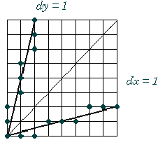
The digital differential analyser is an algorithm for calculating pixel positions along a line (see Fig. 1). This is accomplished by taking unit steps with one coordinate and calculating corresponding values for the other coordinate. The DDA algorithm eliminates the multiplication by taking advantage of raster characteristics, so that unit steps are taken in either the x or y direction to the next pixel location along the line.
However, the calculation are slowed by the divisions needed to set increment values, the use of floating-point arithmetic, and the rounding operations [RUFE95], [SKAL92].

FIG. 1. DDA Algorithm
A more efficient line algorithm to determine pixel position, developed by Bresenham, finds closest integer coordinates to the actual line path using only integer arithmetic. We need do decide between two pixels choices at each x position. Starting from the left endpoint of the line. We need to determine whether the next point along the line (Fig. 2) [RUFE95], [SKAL92].
Fig. 2. Bresenham's Algorithm
Whenever a picture contains opaque objects and surfaces, those that are closer to the eye and in the line of sight of other objects will block those objects from view. The blocked or hidden surfaces must be removed in order to a realistic screen image. The solution and removal of these surfaces is called the hidden-surface problem. The solution involves the determination of depth and visibility for all the surfaces in the picture. There are many different hidden-surface algorithms, but no one of it is best.
The Z-buffer algorithm essentially keeps track of the smallest z coordinate (also called the depth value) of those points which are seen from pixel (x, y). These Z values are stored in what is called the Z buffer.

Fig. 3. Z-Buffer Algorithm
Let Zbuf(x, y) denote the current depth value that is stored in the Z buffer at pixel (x, y). We work with the (already) projected polygons P of the scene to be rendered [RUFE95], [SKAL92].
The Z-buffer algorithm consists of the following steps:
In plotting a mathematical surface described by an equation z = F(x,y),
where xmin ![]() xmax and ymin
xmax and ymin ![]() ymax, we could use any
of the hidden-surface algorithms. However, these general algorithms are
inefficient when compared to specialized algorithms that take advantage of the
structure of this type of surface.
ymax, we could use any
of the hidden-surface algorithms. However, these general algorithms are
inefficient when compared to specialized algorithms that take advantage of the
structure of this type of surface.
Each plotted x and y constant polyline outlines a polygonal region on the plotting screen [RUFE95].
The algorithm is based on the following observations:
Implementation of the visibility condition uses a min-max array A, of length H (that of the plotting device), which contains, at each horizontal pixel position i, the maximum (and/or minimum) vertical pixel value drawn thus far at i. Selection of the max results in a drawing of the top of the surface and the min is used to render the bottom of the surface.
This algorithm is working in object space and is based on that every edge is conjunction of two faces. In step one we eliminate invisible faces. We divide faces at potentially visible and invisible. In another step we divide edges at three types:- invisible edge - conjunction of two invisible faces- potentially visible contour edge - conjunction of invisible and potentially visible faces- potentially visible edge - conjunction of two potentially visible facesIn case non-convex entity we need to know, whether potentially visible face is not covered with another face. For each point of edge we determine number of covered faces. If this number is equal to zero we can draw it.

Fig. 4. Appel's Algorithm
Algorithm animation is a very strong tool, which could make us ponder and precisely understand this algorithm. It provides a possibility to show the algorithm from different point of views and so intelligible explain hardly understandable parts of the algorithm [BROW87].
The basic constrain is to have for each view proper window on screen and each view should change during run of the program. User should be able to decide what and where will be shown and choose detailed pieces of information or zoom only on parts of the algorithm in which he is interested in. Besides algorithm animation we can for better algorithm understanding animate also input and output data and interdata dependencies a compare complexity and quality of the algorithms [BROW87, MYER86].
There exist more models in order of end groups of users.
This model allows programmer to animate any algorithm but it requires not only complete knowledge of then algorithm but also character of input and output data in this model. It is relatively easy to create new animation on new way of animation view.
The whole sequence could be divided into three parts: the algorithm alone, input generator which can obtain data from file, or generate it as random data and last part is graphic view.The programmer decides which ways and methods will be used. On this model follows up
This model also depends on used algorithm, input and output data but it doesn't enable the user to modify the algorithm and character of graphical views and input data [BROW87], [STUC91].
The last but not least is:
Dynamic documents, called scripts, are such as text files in which end-user can not only define the input data but also choose the best way of graphical display for any part of the animated algorithm. The differences between programmers model and this model is that the end-user can not create new way of display. He can use only methods implemented in the animation environment by programmer. But he can create new points of view, windows for animation of special parts of algorithm, etc..
One of the suitable methods for explaining the difficult or new algorithm to users is to generate an animation on a videotape. The author of the animation like this can proceed according to the programmers model or the model for dynamic documents. Because the end-user can not modify this animation, the author must have it in mind. He must choose input data which represents all categories of inputs and describe strange of algorithm [BROW87].
We animated a basic algorithm of computer graphics. Especially, there was processed the algorithm for rasterization of lines.
Animations are devided in two parts. As a first part, the viewer can see meta-code of the algorithm and a picture. On this picture we declarative mathematics side of the algorithm. Later you can see on the display some mathematics formulas, as an explanation of the algorithm.
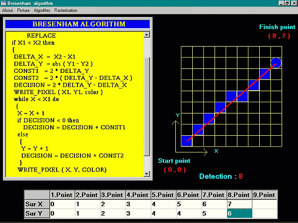
The second part is devided in three videosequencies. In the first one, on the left side of screen, is the meta-code of algorithm. On the right side of screen is rasterization's grid. On the bottom of screen is is grid with co-ordinate of pixels. For good implementation of algorithm, when line in meta-code of algorithm is actived and on the line is calculated Y-coordinate or X-coordinate, then on the grin with co-ordinate wrote actual values of pixels and on rasterization's grid draw rectangle, who represented raster pixel. For DDA algoritm we must calculate line's direction. This is describe up-right values grid. For Bresenham algorithm for line we must calculate, except other values, decision. This is the basic algorithmic variable.
In the algorithm DDA is calculate co-ordinate y or x in the real arthmetics and we must round of number. Bresenham algorithm go ahead, that operation float radix point cant not apply.

Fig. 5. A shortcut from animation of Bresenham algorithm.
On the video is displayed algorithm Z-buffer in action on cube. As a first are displayed and explained the algorithm and the calculating of z-coordinate. Then the screen is divided to the four parts. In the single parts are the pseudocode, z-buffer, frame-buffer and in the fourth part is the window, where is depict one surface of cube in raster. The pseudocode is stepped by single row and in the others parts the user can follow current process. In the z-buffer's window are assign values by the z-coordinate of cube pixels and in the frame-buffer's window are displayed this pixels of corresponding color.
The second animation presents algorithm of rendering mathematical surfaces by means of floating horizon. At first there are shown some graphs created by this algorithm. Then, like in the Z-buffer algorithm, we single explained function of algorithm. In the second section is displayed this algorithm on the graph sin(2*x+cos(y)). The screen is divided to four parts. In the first is pseudocode of algorithm, in the second is our graph depict step by step like the algorithm is going. Then there is cover of the graph and the data from cover. At the end there are shown some negatives of this algorithm.
In this paper we presented some methods of the algorithm animation. The whole work has educational character. The tape with animated algorithms will be use in the education's process. The main feature of this work is intelligibility of the animation and after seeing the animation the end-user must understand the algorithm and know all about its advantages and disadvantages. The video will be presented as a part of the presentation of this work.