|
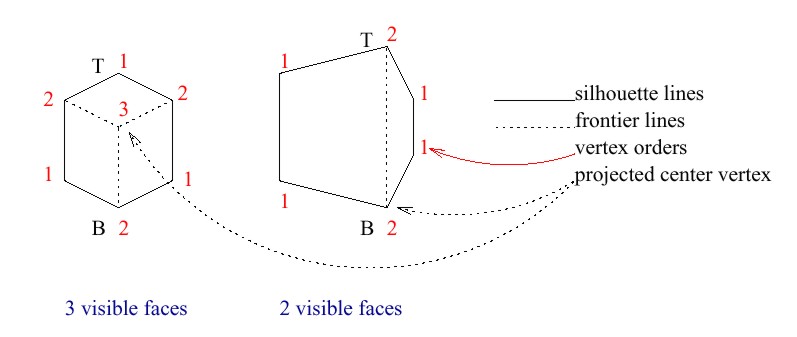
The outline of a macro-cell projection is defined by the projections of the vertices of all visible macro-cell faces. It is made up by either 4 (one macro-cell face is visible) or 6 (two or three macro-cell faces are visible) projections of vertices. These projections will be referred to as silhouette points. Each vertex is assigned an order, which is the number of visible macro-cell faces, that the vertex is part of. The projection of a vertex v is a silhouette point, if and only if the vertex v has an order of one or two.
Silhouette lines connect silhouette points to form the boundaries of the macro-cell projection. The projection of the center vertex is connected to the projections of all other vertices, which have an order that is greater than one, by frontier lines. Frontier lines mark the boundaries between the projections of visible macro-cell faces. Figure 3 shows two examples of macro-cell projections.
The rasterization process moves from the top (T) to the bottom (B) silhouette pixel of the projection. Rasterized silhouette lines define a left and a right bound pixel for each scan line. For each pixel in between, a local ray is cast. The position of each pixel relatively to intersections of the scan line with rasterized frontier lines indicates, through which macro-cell face the local ray enters the macro-cell. Thus, ray entry points, the starting points of local rays, can be found efficiently by simply intersecting each ray with the plane of its entry face.