![[CESCG logo]](../../CESCG/images/cescg98.small.gif)
|
Using VRML for creating interactive demonstrations of
physical models
Karel Cibulka, Jiri Zara
xcibulka@hwlab.felk.cvut.cz, zara@fel.cvut.cz
Department of Computer Science and Engineering
Czech Technical University
Prague, Czech Republic
|
![[CESCG logo]](../../CESCG/images/cescg.small.gif)
|
Abstract
We present utilization of VRML language as a tool for interactive visualisation
of physical simulations. Techniques for creating interactive and visual
simulations are analysed and practically implemented in form of a VRML
library. Primary effort is focused to the real-time interactive work, but
the off-line visualization of large data sets obtained from other simulation
systems is allowed as well. Examples show that the proposed approach is
easy to use, flexible and powerful enough to visualize both simple and
more complex processes.
1 Introduction
With growing number of powerful computers being available to larger number
of people, utilization of computers for more tasks is increasing. One of
possible domains for using them is computer simulation of a real world
or more particularly of physical phenomena. There are not many simple and
yet available tools or programs, that enable creating that kind of simulations,
that is why users are forced to create them by themselves. Creating of
the simulations by this way is not acceptable for many users. The approach
of using a well-known and fairily available programming language is tested
as a solution of previously presented problem, so that user can use our
work for creating of simulations with minimal programming experience. VRML
language is chosen as a primary modeling environment for its capability
to create interactive 3D worlds, wide availability on all types of computers,
and great extendibility through scripts.
The structure of this paper is organized as follows. Basic simulation
concepts of real world simulations on computers are discussed in Chapter
2. In Chapter 3 these simulation concepts
are implemented in VRML language. A group of utilities for assembling of
simple simulations (Simulation Tool Box (STB) library) is presented in Chapter 3.1.
Experimental simulations constructed with STB library are presented in Chapter 4.
2 Simulation and visualisation
The simulation and visualisation of real world is a very extensive task,
with a variety of problems and subtasks. For our purposes we will simplify
the problems, theoretically covering the task of mathematical solving and
representing of simulated phenomena. Let us assume, that a user is able
to express the mathematical representation of a problem and he or she wants
to embed this mathematical model only into a visual representation. If
simulations are examined by means of their visual representation in computers,
they can be divided into two separate groups.
The first group, called "off-line" simulations, represents simulations,
in which a user obtains computed values from a mathematical program outside
simulation. Computation related to creating of simulation key values is
not directly inside the simulation.
The second group, called "on-line" simulations, represents simulations
containing some sort of control that implement mathematical model of simulated
phenomena. The user can change simulation parameters interactively, thereby
he or she can immediately affect behaviour of the simulation.
Implementation of simulations and their visualisation can be generally
divided into several parts (as shown in Figure
1):
-
Visual model, which represents simulated phenomena or behaviour.
-
Graphical User Interface, dedicated to controlling of input values, visual
representation and the run of simulation.
-
Simulation control, which controls behaviour of simulation in response
to user or other events.
Figure 1: Basic simulation parts and their communication.
Each part of simulation is discussed in following chapters.
2.1 Visual model
Objective of all simulations is to present results of mathematical computations
(generated from an experimental theory or from an observation of real phenomena)
to a user in a readable and understandable form. Primarily it is in form
of tables of numbers, graphs or animated visualisation of simulation. The
focus is set on the third form of visualisation, which enables creating
applications in an interesting visual form, understandable also for users
that are not theoretically familiar with presented problems.
2.2 Graphical User Interface
Main task of GUI is to create a visual interface between a user and a simulation
control. This represents a set of visual displays that show actual state
of simulation and simulated phenomena (e.g. different types of indicators,
such as digital displays), and a set of control elements that allows interactively
interfere with simulation (e.g. different types of buttons, controllers).
2.3 Simulation Control
The tasks of simulation control can be divided into two parts, each communicating
with the other. The first part is the simulation control related to GUI.
It traces user requests to change simulation parameters and supplies values
for displays in GUI. The second part is related to control the run of simulation.
It changes visual representation of simulation based on simulation parameters
supplied from mathematical model (previously presented on-line type of
simulation), or from other simulation program (off-line type of simulation).
Particular properties of this division is discussed in next two chapters.
2.3.1 Off-line simulation
This set of simulations uses an independent program, which can implement
sophisticated algorithms and procedures for precise creation, representation
and problem solution. Problems solved by this program can be so complex,
that the results cannot be computed in real time. Then the computed data
are preprocessed and finally sent to the simulation control. The off-line
simulation present them to a user. The advantage of this approach is precision
of computation model, which is based on program dedicated to solve simulation
problems. This program can compute large simulation problems independently
on user's machine, which is used only for presenting results to a user.
In this case the visualisation is almost independent on mathematical model
previously used. On the other hand the user is not able to view result
dependecy on change in input parameters in real-time (e.g. immediately).
The Figure 2 represents block diagram
of off-line simulations.
Figure 2: Off-line simulation scheme.
2.3.2 On-line simulation
For primitive simulations, which do not need complex computations, the
solving of problem can be incorporated into simulation control. This type
of simulation can reflect user's changes of input values of simulation
immediately (or almost immediately, depending on implementation of simulation
computation algorithm). Main disadvantage is restriction to mathematical
or algorithmic simple simulations, because computation must be performed
in real time, during simulation presentation. Simulation is limited to
user's computer resources, which are already used in visualisation engine.
The second disadvantage can be the implementation of simulation solving
engine directly in simulation model. For new algorithms used for solving
the same problem it is needed to change simulation control. This type of
simulations can be divided into two groups, each of them is applicable
for different tasks:
-
Passive on-line simulations. Simulation solving engine computes
behaviour of visualisation model once for one change of input values and
then it "sleeps" until input values are changed again. This group is analogy
of off-line simulations with the exception, that off-line simulations do
not contain solving engine inside simulation. Passive simulations can be
also used for simulating phenomena, which are independent of time (e.g.
simulation of non-kinetic models). One good example can be simulation of
reflection or refraction of rays inside a user defined and modified environment.
-
Active on-line simulations. Simulation solving engine computes continuously
behaviour of visualisation model based on current state of input values
and on current time inside simulation. Such models can have kinetic equations
implemented in simulation solving engine, which computes e.g. position
based on actual time of simulation. This sort of simulations assume knowledge
of the solution based on time, and it must be sufficiently simple to be
computed in real time. Active simulations implement only simple simulations;
main advantage of this solution is immediate response to user changes of
input values. An example can be simulation of pendulum, based on all the
parameters defined by the user (e.g. gravity).
Figure 3 shows block diagram of both
on-line simulation groups.
Figure 3: On-line simulation scheme
3 VRML
The Virtual Reality Modeling Language (VRML) is a file format for describing
interactive 3D objects and worlds. Now it is defined as ISO standard ISO/IEC
14772-1;1997, for further information look at web site http://www.vrml.org/Specifications/VRML97/index.html.
VRML is designed to be used on the Internet, intranets, and local client
systems. VRML is also intended to be a universal interchange format for
integrated 3D graphics and multimedia. VRML may be used in a variety of
application areas such as engineering and scientific visualization, multimedia
presentations, entertainment and educational titles, web pages, and shared
virtual worlds. VRML has been designed to fulfil several requirements:
-
Enable the development of computer programs capable of creating, editing,
and maintaining VRML files, as well as automatic translation programs for
converting other commonly used 3D file formats into VRML files.
-
Provide the ability to use and combine dynamic 3D objects within a VRML
world and thus allow re-usability.
-
Provide the ability to add new object types not explicitly defined in VRML.
-
Capable of implementation on a wide range of systems.
-
Emphasize scalable, interactive performance on a wide variety of computing
platforms.
-
Enable arbitrarily large dynamic 3D worlds.
VRML is capable of representing static and animated dynamic 3D and multimedia
objects with hyperlinks to other media such as text, sounds, movies, and
images. VRML browsers, as well as authoring tools for the creation of VRML
files, are widely available for many different platforms. VRML supports
an extensibility model that allows new dynamic 3D objects to be defined
allowing application communities to develop interoperable extensions to
the base standard. There are mappings between VRML objects and commonly
used 3D application programmer interface (API) features. Each VRML file:
-
implicitly establishes a world coordinate space for all objects defined
in the file, as well as all objects included by the file
-
explicitly defines and composes a set of 3D and multimedia objects
-
can specify hyperlinks to other files and applications
-
can define object behaviours
Main structure of language is based on object oriented programming concepts.
All parts of VRML scene is defined by group of object definitions in the
source text of scene. It is defined by "nodes", in OOP terminology they
can be called objects. Nodes have defined internal data - "fields" with
default initial value, which can be redefined. Each node can contain input
and output fields, called eventIn and eventOut. They generate or receive
events to/from other nodes. This events are for example changes of object
position or node's field value. For passing events between nodes mechanism
of routes is created. ROUTE keyword defines interconnection between
eventIn of one node (destination of event) and eventOut of second node
(source of event).
Nodes are grouped by their functionality into several categories:
-
Visible geometry Nodes: Nodes representing basic geometric primitives
(Box, Sphere, Cone, Cylinder), extended
geometric primitives (IndexedFaceSet, Extrusion, Text),
special objects (IndexedPointSet, IndexedLineSet). Nodes
used for changing visual representation of geometry by defining its colour
(Material) and textures (ImageTexture, MovieTexture).
Nodes used for changing background of scene (Background) and nodes
adding special visual effects (Fog).
-
Invisible geometry Nodes: These nodes are not directly visible,
but they can affect visual representation of other visible nodes in scene.
Nodes used for defining lights (PointLight, SpotLight)
belongs in this category. Node used for predefining starting location of
viewer (Viewpoint)
-
Sensors: Invisible nodes which enables direct interaction with user
(TouchSensor, PlaneSensor, CylinderSensor).
Nodes detecting movement of user (ProximitySensor) or other events
created by user movement (VisibilitySensor).
-
Control Nodes: Nodes used for interpolating values between defined
set of key-values (ColorInterpolator, PositionInterpolator,
RotationInterpolator, ScalarInterpolator), time generator
(TimeSensor) and script nodes containing programming code in Java
or JavaScript (Script).
-
Browser communication: Nodes used for interaction with host browser
(NavigationInfo) or used for creating links to other HTML or VRML
documents (Anchor).
-
Special nodes: Nodes used for grouping other children nodes thus
enabling creation of hierarchical structure of nodes in scene (Group,
Transform, Billboard, Collision, Switch,
LOD). Sound emitting node (Sound). Node changing style
of text nodes (FontStyle).
3.1 VRML and simulation
Basic structure of interaction process in VRML scene is on Figure
4 .
Figure 4: Scheme of interaction process in VRML
A user does some interaction with VRML scene, affecting Sensor node. Sensor
node then generate an event, which is processed through Script and is sent
to TimeSensor. TimeSensor starts generating time events, used for interpolating
in Interpolator node. Output of Interpolator node is routed to Geometry
or other node. This is a very basic concept, some of described nodes can
be bypassed or some other can be inserted into the event route. In the
VRML scene more of these event routes can be used independently or they
can affect each other.
Simulation parts described in Chapter 2
can be implemented in VRML in the way schematically described on Figure
5 .
Figure 5: Simulation structure in VRML
Simulation control part controls operation of the whole VRML scene. It
is implemented by Script node. Script gets input values from input
GUI nodes, creates values for output GUI nodes and communicates with scene
geometry. In off-line simulations Script does not compute any new values
for scene geometry, it controls only "playback" of precomputed values stored
in interpolator nodes. Scripts in on-line simulations are more complex,
they must compute actual values of simulation based on values from input
GUI nodes. Script node is interconnected with TimeSensor node, which is
used for generation of simulation time.
GUI is divided into two parts: input components (nodes used for user
input) and output components - displays (nodes presenting data to user).
These components can contain sensors (input components only), visible geometry
and control scripts implementing behaviour of component. Input and output
events from them are then routed to control script.
Simulation geometry contains geometry used for visualization of simulation
subject. For off-line simulations there is also an interpolator node, used
in conjunction with TimeSensor for playback of precomputed key values of
simulation.
3.2 The Simulation Tool Box
Based on concepts introduced in Chapter
3.1, library of basic elements is proposed. It contains basic components
used for building simple simulations. This library is called Simulation
tool box or STB. It is created using concept of external VRML prototypes
(EXTERNPROTO), which enable to create new types of nodes. The
nodes are defined outside main simulation VRML file and they are imported
using EXTERNPROTO keywords. Main simulation file then contains
only references to used external nodes, geometry used for visualization
of simulation and main simulation script.
STB library is divided into three parts:
-
Input GUI components - Components used for data input; this part
implements set of buttons, scrollbars, knobs etc.
-
Output GUI components - Components used for displaying data; this
part implements set of indicators, gaugers, displays etc.
-
Other components - Set of auxiliary components, designated for simplifying
common tasks (e.g. steppable TimeSensor or components used for data conversions
between different VRML data types).
4 Examples
For demonstration purposes few simple examples of simulations in VRML are
created. In this chapter implementation of STB library from Chapter
3.2 and its utilization in a pendulum example is presented.
4.1 Simple STB library implementation
Example of simple STB library contains set of usable components, implementing
GUI components and simple auxiliary components.
Input GUI components in library are constructed from visible geometry,
used in conjunction with VRML sensors and control script to convert user
input to VRML data. Data types supported by STB library for input components
are following:
-
SFBoolean: Implemented by set of buttons (inpButton).
-
SFInt32: Implemented by switches (inpMultiSwitch).
-
SFFloat: Implemented by set of scrollbars, knobs a digital calculator
(inpScrollBar, inpKnob, inpFloatDigitalCalc).
Other data inputs can be done by using standard types and converting components
(e.g. three SFFloat data inputs can be converted to one SFColor
data value).
Output GUI components utilizes scripts. They then control visible geometry,
used for displaying data values. Data types supported by STB library for
output components are following:
-
SFBoolean: Implemented by indicators (disShowBool).
-
SFInt32: Implemented by indicators with multiple shapes or colours
(disShowInt32).
-
SFFloat: Implemented by set of scrollbars and knobs (disShowFloat,
disShowFloatKnob) or by digital display (disShowFloatDigital).
-
SFString: Components used for creating text labels (disTextLabel).
Other VRML types can be converted to supported data types (e.g. SFColor
converted to three SFFloat values can be displayed by three scrollbars).
Auxiliary components are various data converters used for converting
simple VRML data types (SFBoolean, SFInt32, SFFloat)
from/to other data types (e.g. SFColor). They contain only a converting
script, which converts input data types to different output data types.
During conversion it is possible to adjust input value (e.g. by linear
scaling). Examples of this conversion components in STB library are:
-
conBoolInt32: Converts SFBoolean to two possible SFInt32
values.
-
conFloatVec2: Converts two SFFloat values to one SFVec2f
value.
-
conColFloat: Converts SFColor value to its three SFFloat
components.
Next set of auxiliary components are supporting scripts, like steppable
TimeSensor and script implementing simple control panel. Steppable
TimeSensor component (stepTimeSensor) is able to generate
time events like standard TimeSensor, or time can be stepped by
defined time slice forward or backward. Generated time can be also accelerated
or decelerated with respect to real time (e.g. one second in simulation
can be 10 seconds in real time).
Table 1 shows program interface (EXTERNPROTO)
of a component from STB library. This EXTERPROTO is included in
source code of VRML scene. Then the component is used in the same way as
standard nodes, that is by its name and definition of new values.
EXTERNPROTO inpScrollBar [            # Scroll Bar input component
  field MFNode sbKnobObject           # scroll bar's knob geometry
  field SFFloat minValue              # Min/Max range of data
  eventIn SFFloat set_minValue
  field SFFloat maxValue
  eventIn SFFloat set_maxValue
  field SFFloat value                 # data value
  eventIn SFFloat set_value
  eventOut SFFloat value_changed
] "inpScrollBar.wrl"
|
Table 1: Programming interface of inpScrollBar component from
STB library
Implementation of each component is divided into four parts, each part
has following meaning:
-
Component header - contains VRML file header and definition of PROTO
header, in which all public data fields and events of component are defined.
-
Component geometry - contains sensor and geometry of component.
This part of component is visible to a user.
-
Component control script - contains script, which is controlling
behaviour of component, controls data input, output and changes to component
geometry.
-
Component routes - this part defines ROUTEs used for linking
geometry and script of component.
Figure 6 shows some examples of GUI components.
Figure 6: Examples of GUI components
4.2 Experimental model
We have developed several experimental simulations using STB library presented
previously in Chapter 4.1. One of them
is simple mathematical pendulum, implementing well-known simplified kinetic
equation (see Figure 7).
Figure 7: Kinetic equation of mathematical pendulum
The equation is implemented in simulation's control script. The script
receives time events from TimeSensor, computes new actual position
(rotation) of a pendulum and updates corresponding geometry. The user can
change the gravity, the length and the starting angle of the pendulum.
Example of screen with simulation in phase of setting input values is in
Figure 8 .
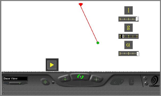
Figure 8: Setting parameters of pendulum example
When the simulation is started, pendulum starts moving, according to the
parameters entered by user. Set of associated displays shows current values
of interest (the angle, the position of a pendulum). Figure
9 shows example of moving pendulum.
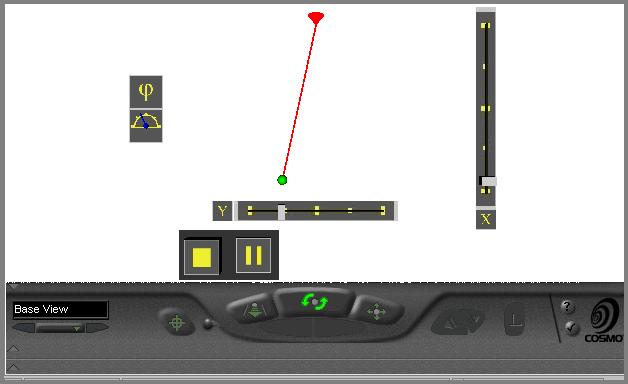
Figure 9: Running simulation of pendulum example
The simulation VRML program consists of 5 parts:
-
VRML file header - contains VRML header and EXTERNPROTOs
for components included from STB library.
-
GUI part - contains definition of GUI using STB library components.
-
Simulation geometry - geometrical representation of mathematical
pendulum.
-
Simulation control - a script which controls behaviour of scene.
-
ROUTEs definitions - definitions of event links in scene.
All calculations needed by simulation are implemented by Script node in
simulation control part.
5 Conclusion
The use of VRML as general purpose simulation tool shows several aspects
of this language. The language is well defined and makes possible to create
a large set of interactive simulations. Concept of off-line simulations
can enable its usability to visualize more complex simulations.
Most of current problems with VRML simulations are related to two following
problems. The first problem is computational power (strictly speaking display
performance) of wide available computers. They are not yet powerful enough
to animate complex scenes smoothly in real time. We hope that this problem
disappears in near future, as computer industry is innovating every day
with incredible speed. The second problem is linked with VRML implementation
in browsers. VRML as ISO standard is existing about one year and this affects
quality of currently available VRML browsers. For working simulations the
support of script nodes is needed (particularly Java or JavaScript language
support). STB library utilizes concept of EXTERNALPROTO definitions,
but not all browsers always support these properties of VRML language correctly.
Presented STB library is only a part of more complex work, which implements
set of tools for simple and interactive construction of simulations in
VRML. STB library implements basic components used in common simulations
in VRML, like GUI and auxiliary components. It can be used as a standalone
library, components can be imported into any other VRML scenes. Advantage
of this concept is independence of current implementation of components
in STB library if its program interface remains the same. Components can
be upgraded by means of visual representation and scene, which is using
them, does not need to be changed. Disadvantage of this concept is necessity
of manual including of EXTERNPROTOs definitions into VRML file,
because VRML prohibits to import them by single keyword.
STB library and examples presented in Chapter
4 are tested on well-known CosmoPlayer browser from SiliconGraphics.
This browser (by our experience) implements most of VRMLs with minimum
errors.
This article is focused on basic simulation concepts and their testing
in implementation of on-line simulations. We are working on extending of
STB library with tools for visual construction of scenes. We also pay efforts
toward generalization of STB into form, usable by other available products
(e.g. CosmoWorlds). The second task is creation of experimental off-line
simulations, which will utilize general purpose simulation systems as a
base source of simulation values. Example of this system is TeleSimulation
Project - Simulation of multidisciplinary systems via Internet.
6 References