![[CESCG logo]](../../CESCG/images/cescg98.small.gif)
Martin Doležal
xdolez00@stud.fee.vutbr.czDepartment of Computer Science & Engineering
Faculty of Electrical Engineering and Computer Science
Technical University of Brno
Brno / Czech Republic
![[CESCG logo]](../../CESCG/images/cescg.small.gif)
|
|
Realistic rendering using ray tracing
Martin Doležal xdolez00@stud.fee.vutbr.czDepartment of Computer Science & Engineering Faculty of Electrical Engineering and Computer Science Technical University of Brno Brno / Czech Republic |
|
Rendering is a general term that describes the overall process of going from a database representation of three-dimensional objects to a two-dimensional projections on a view surface.
One of the most known rendering method is Ray Tracing. In base algorithm it is the method where the light ray is traced from viewer point to the scene. This algorithm is also called as Recursive Ray Tracing. Pictures produced by this method seems to be very clear and sharp when compare with real world, but still very realistic. It is not so time-consuming as others methods based on physical essence of light energy.
Keywords:
rendering, ray tracing, Beriér patch.Created picture has a specific raster. At a point that correspond to a raster cell, the surface visible and hence color and intensity at that point are obtained by tracing array backwards from the eye thought the point of picture into the scene. If this ray intersects an object, then local calculation will determine the color that is the result of direct illumination at that point. This is light from source directly reflecting from the surface. If the object is partially reflective, partially transparent or both, the color of the point in the image plane will include a contribution from reflected and transmitted rays. These rays must be traced backward to discover their contribution. Determining a color for each of these rays may require the tracing of further rays at other intersections with objects. To determinate the color of the original point in the viewing plane, this set of rays must be traced backward trough the scene. Note at this point, it produce the picture for only one viewer point and direction (image plane), therefore we need new calculation if viewer point or direction is changed.
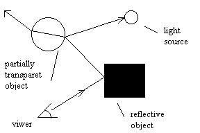
Pic. 1: A simple example demonstrating recursive ray tracing.
Each time a traced ray intersects a reflect surface it produce a reflected ray. The reflection direction is given by: R = I + 2N cosa
where I is unit vector representing the incident ray direction, witch is the same as the light vector, and N is the surface normal vector.
There we have two types of illumination - direct and global. Direct illumination is light incident on a scene from a light source or a number of light sources. A surface receives light directly from a source. Global illumination represent the light with origin of source light incident on a surface element. It originate from the interaction of direct light with reflective and transparent objects.
In Phong illumination model: Iphong = Idiffuse + Ispecular + Iambient
where Idiffuse and Ispecular are terms originate from direct illumination and the Iambient term originate from diffuse light of the scene. Ambient term is there modeled as a constant.
A ray striking a partially or wholly transparent object is refracted owing to the change in the velocity of light in different media. The angles of incidence and refraction are related by Snell’s law:

The refractin direction is given by: ![]()
where ![]() and
and 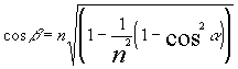 and I = -L
If a ray is traveling from a more to a less dense medium then it is possible for the refracted ray to be parallel to the surface. In this case incident angle is called as the critical angle. If incident angle increased over critical angle, total reflection occurs.
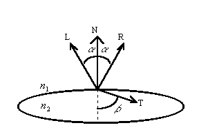
Pic. 2: Reflection and refraction.
In ray tracing, to this model are added two more terms. These are the contributions from a reflected ray incident on the surface element and from a transmitted ray incident on the surface element, originating from elsewhere in the scene. Both these are traced rays whose color contributions are returned by the recursive ray tracing procedure.
![]()
where ![]() is coefficient of reflected light and
is coefficient of reflected light and ![]() is coefficient of transmitted light.
is coefficient of transmitted light.
This expression points to recursive process where ![]() invokes an equivalent expression at the next surface intersected by the transmitted ray, and
invokes an equivalent expression at the next surface intersected by the transmitted ray, and ![]() invokes an equivalent expression at the next surface intersected by the reflected ray. Thus in any multi-object scene we can consider that reflection from a visible element will originate from three sources: ambient light, direct light sources and traced ray of light concentrated along particular directions because of interaction between objects.
invokes an equivalent expression at the next surface intersected by the reflected ray. Thus in any multi-object scene we can consider that reflection from a visible element will originate from three sources: ambient light, direct light sources and traced ray of light concentrated along particular directions because of interaction between objects.
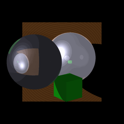
Pic. 3: Picture generated by Ray Tracing method.
One of the most known cubic surfaces is Beziér patch. A point on the surface patch is given by a biparametric function and a set of basis or blending functions is used for each parameter. Beziér patch using basis function of degree tree is defined as:
![]()
tree-dimensional surface generated from the cartesian product of two curves., where each term in the sum is a product of control point Pij and a blending functions Bi, Bj. The set of basis functions given for cubic polynomial:
![]()
![]()
![]()
![]()
where ![]() for basis function of any degree n is obtained from expression
for basis function of any degree n is obtained from expression
![]()
where ![]() is the binomial coefficient defined as:
is the binomial coefficient defined as: ![]()
![]() .
.
Algorithms that scan surfaces represented by bicubic parametric patches divide into two categories. The first is rendering directly from the parametric description, and the second is approximating the surface by a polygon mesh and scanning this approximation.
The second algorithm is certainly the easier to implement and is computationally less expensive. The ask is to generate a planar polygon mesh from a surface patch. The mesh is a result of two-dimensional sampling of biparametric cubic surface patch. Received rectangles are diagonally divided into two triangles. Surface is now representing by the set of triangles.

Pic. 4: Beziér patch.
In general, a finer polygon resolution will be necessary to eliminate the visibility of linear discontinuities. This problem can be solved by surface normal interpolation where the surface normal of any triangle surface point is computed as interpolation of normal vector of that triangle and normal vectors of surroundings triangle’s. The solution of normal vector interpolation false if using 3D textures. There are others methods where the mesh is subdivided where it is necessary.
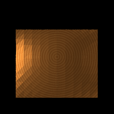
Pic. 5: Beziér patch with 3D texture.
This article presents a brief explanation of ray tracing rendering method and implementation of Bézier patches. Pictures presented in this document were created by program witch is based on maintained knowledge’s and is written by author. At the end I would like to thank to my work leader Dr. Ing. Pavel Zemčík for help.