Abstract
One of the major goals in real-time computer graphics is
to achieve high realism of rendered images without compromising rendering
speed too much. Frame update rate requirements are especially demanding
in the area of entertainment software. Player immersion is directly related
to both the number of frames displayed per second and the visual quality
of the images rendered in each frame. Traditionally, these two goals have
largely excluded one another. In recent years, however, standard desktop
hardware has become powerful enough to make real-time rendering of convincing
virtual environments possible.
This paper describes the rendering
engine of Parsec, a three-dimensional computer game we are currently developing.
In this, we are focusing on those parts of the rendering process that are
not part of the standard transform-clip-draw pipeline for polygonal objects.
We are rendering multiple layers to achieve different effects with techniques
specifically suited to the nature of these effects. We use an image-based
rendering approach to render an infinitely far-away background. Particle
systems are employed to render effects that cannot easily be achieved with
polygonal objects. Our software-renderer also harnesses multi-layer rendering
to decouple specific rasterization tasks in order to gain significant speed-ups.
Keywords: multi-layer rendering,
image-based rendering, environment mapping, computer games, real-time graphics,
particle systems, special effects, flare, glare.
0. Contents
1. Introduction
The developer of contemporary three-dimensional entertainment
software constantly faces the problem of two largely contradictory goals:
First, rendering speed has to be very
high to achieve the frame update rates necessary. If too few images are
rendered per second the virtual environment will not be very convincing
and enjoyable for the player. The feeling of immersion is easily lost when
the frame rate is below, say, 20 frames per second (fps), and computer
games often demand frame rates of 30fps and more. Even more important than
high peak frame rates is the requirement that the frame rate be almost
constant in order to facilitate smooth animation. A somewhat lower but
largely constant frame rate is clearly preferable to widely varying rates
with a higher peak frame rate.
Second, the quality of the generated
images is also crucial to achieving player immersion. The more aspects
of reality are captured in those images, the better the feeling of "actually
being there".
The key to rendering a convincing
virtual environment in real-time is to make well-considered trade-offs
between visual quality and rendering speed. If different parts of a scene
are rendered using different techniques well suited to these parts, significant
speed-ups can be gained in contrast to rendering an entire scene with a
single rendering technique.
Hence, the idea of rendering the projected
image of a scene in multiple passes and using various object representations
is very important to combining high visual quality and rendering speed.
In this paper we are going to look at exactly those aspects of the rendering
engine of Parsec, a three-dimensional computer game we are currently developing
[Parsec]. Parsec is a space-fight game specifically targeted at network
gameplay. The current version can be played by four simultaneous players
over an IPX network. Since the background of a Parsec screen depicts mostly
unreachable parts of outer-space, image-based rendering is naturally suited
to rendering this background. We use multiple layers of cubic full view
panoramic images to render nebulae, stars, and planets, similar to environment
mapping with cubic environment maps. Objects like spacecraft are polygonal
models rendered using a graphics pipeline employing BSP trees. Special
effects are rendered after polygonal objects, mostly using particle systems.
Additional lens flare effects can be rendered last.
2. Related work
In this section we are going to briefly review research work
concerned with those fields of computer graphics we have drawn upon in
our own work, and which have proved to be very useful for our particular
application.
2.1 Image-based rendering
Image-based rendering and environment mapping techniques
are particularly suited to rendering an infinitely far-away background
of an outer-space setting, that is, for part of our application. [Gree86]
mostly considers different types of environment maps as they are used for
reflection mapping [Blin76]. Nevertheless, Greenes paper already mentions
that world projections onto environment maps can be used to render a far-away
background without explicitly modeling it, e.g., a sky backdrop. In recent
years, the concept of image-based rendering has received a lot of attention,
often also removing the requirement that the rendered background be far
away. [McMi95] provides a consistent conceptual framework to all these
techniques via plenoptic modeling, using the so-called plenoptic function.
Since a single panoramic image is only correct for a single viewpoint,
view interpolation and morphing may be used to seamlessly migrate from
one viewpoint with an available panorama to the next [Chen93]. Recently,
image-based techniques have also entered the marketplace for consumer-products.
The work in [Chen95] still requires a specialized viewer, though, that
is capable of cylindrically distorting the employed cylindrical panoramic
images on-the-fly. Cylindrical panoramas also restrict the possible camera
rotation, since they are not full view. Another problem may be the need
to track camera motion in order to be able to reconstruct panoramic images.
Video mosaics [Szel96] alleviate this problem. This work is greatly expanded
upon in [Szel97], which provides a technique for creating full view panoramas
from image mosaics. The algorithm presented in this work is able to automatically
register images and calculate texture-maps for arbitrary all-encompassing
objects. The simplest such object still yielding impressive results is
a cube with the viewpoint at its center. The image-based approach can be
combined effectively with the notion of rendering the projection of a scene
in multiple layers [Leng97]. This helps in allocating rendering resources
according to the visual importance of different parts of a scene and their
frequency of change. Rendering multiple layers is an important approach
to exploiting frame-to-frame coherence. We have also used the related idea
of multiresolution compositing [Berm94] to render different parts of a
scene in resolutions particularly suited to them, performing image-composition
afterwards.
2.2 Particle systems
Particle systems are a powerful approach to rendering effects
that cannot easily be modeled otherwise [Reev83]. Particles are assigned
basic properties like appearance and velocity, a huge number of them behaving
in a conceptually identical way [Sims90]. Their visual effect on the viewer
depends largely on the creativity of the modeler, however, who has to creatively
harness the basic functionality provided by such systems. More powerful
primitives, like vector fields [Hilt94], can help in this task.
2.3 Special effects
We have also used work on various other special effects.
[Spen97] describes in detail how glare is caused by the human visual system.
This information can be used to enhance the realism of computer-generated
images by adding bloom and flare lines around very bright objects in a
scene in order to increase their perceived brightness. If those effects
are pre-rendered and used as texture maps during run-time, they can easily
be used in a real-time rendering system. The work in [Reed94] provides
physically-based information about how to render realistic lightning. Nevertheless,
the emphasis is on visual appearance instead of physically exact evaluation.
Particle systems are also used in this work, and we have actually integrated
a modified lightning effect as a "special weapon" in Parsec, utilizing
our particle system.
3. Rendering layers in Parsec
In this section we are going to explain step by step how
each frame in Parsec is rendered. There are four major layers: Panoramic
background, polygonal objects, particles, and additional special effects.
We discuss these layers in the same order as they are rendered.
3.1 Panoramic background
The visual appearance of the background is especially important
in an outer-space setting like Parsec, since large areas of the screen
will be dominated by this background only. In Parsec, the background depicts
large-area nebulae, hundreds of stars only a few pixels in size each, and
other objects that can never be reached by the player, like planets and
stars bright or big enough to justify using textures instead of single
points. Image-based rendering is ideally suited to be used in this case,
but not only because the player can never reach anything being part of
the background. Characteristic astronomical phenomena like nebulae can
simply not be rendered realistically enough using another real-time rendering
technique. Panoramic background rendering is done in four layers. The first
two layers are responsible for nebulae and stars, respectively. Layers
three and four are used for two different types of detail objects. But
first we will have to consider how to represent a full view panorama.
3.1.1 Choosing a suitable world projection technique
To surround the player with a seamless full view panoramic
image, a suitable representation for a world projection [Gree86] must be
chosen. Cylindrical projections, like in [Chen95], are out of the question,
since the player is able to look about without any restrictions. Therefore,
some kind of spherical projection has to be used to achieve a full 360°
view in every direction. Ideally, if we could somehow project the entire
world onto the surface of a sphere centered at the current viewpoint, and
sample this sphere for each pixel on the screen at run-time, we would be
able to render images identical to rendering the entire world. This would
work regardless of camera orientation, as long as the viewpoint (camera
position) stays the same. In our case, even the viewpoint position need
not stay the same, since everything being part of the background is considered
being infinitely far away. Actually, with respect to panoramic background
rendering, the viewpoint is always located at the worlds center. Camera
translation is ignored in this stage of rendering, although it is used
in all other stages, of course.
The first problem with this ideal
world projection is that normally the spheres surface has to be sampled
at discrete points, provided that we cannot always recalculate a color
for an arbitrary surface-point at the time we need it. This would only
be the case if we were able to represent the entire surface procedurally.
At first glance this may seem totally out of the question, but if the world
consists only of procedurally represented nebulae (i.e., solid texturing
functions) this would actually be possible. Still, on-the-fly evaluation
of solid texturing functions is not what we desire for a real-time application,
and we also do not want to restrict ourselves in terms of flexibility regarding
the method employed for creating the actual nebulae. As soon as the sphere
is not represented continuously, we represent the world projection by a
finite set of sampling points. At run-time we could resample such a discretely
sampled sphere to render an arbitrarily oriented view of the world.
The second problem, however, is how
to represent the surface of a sphere by a planar texture. A latitude-longitude
projection has always problems at the poles, for instance. Furthermore,
since we want to use the environment map to render the entire background,
not only for reflections on objects surfaces like in reflection mapping,
we do not want to afford spherical projection of the map at run-time, in
order to be able to display it full-screen. In addition, we want to be
able to exploit standard texture-mapping hardware, which is only capable
of performing planar projections.
Another approach to representing full
view panoramic images, described in [Szel97], is to surround the viewpoint
with an arbitrary, all-encompassing, texture-mapped object centered at
the viewpoint. The textures for this object can be calculated by sampling
the entire world for each texel. At run-time, it is rendered using planar
texture-mapping only. Therefore, graphics accelerator hardware can naturally
be exploited. For all objects other than a cube, the needed textures cannot
easily be created using standard rendering packages, however, which is
why we chose to use a cube surrounding the viewer. We modeled background
nebulae and stars using the freely available POVRay raytracer, employing
procedural techniques. In POVRay, it is particularly easy to specify six
cameras with 90° viewing angles to project the entire world onto the
six sides of a cube, without incurring noticeable seams at the cubes edges.
3.1.2 Panoramic layers one and two: Nebulae and stars
As we have stated before, nebulae and stars are rendered
in two independent layers. The reason for this is mainly texture-map resolution,
that is, memory-consumption of the employed environment maps. The first
cubic environment map (layer one) is comprised of six 256x256 RGB textures,
one for each side. Since nebulae are rather diffuse phenomena and bilinear
texture-filtering is used at run-time, this resolution is high enough.
The second cubic environment map (layer two) is comprised of a single 256x256
alpha-only texture, used 24 times, that is, four times per side. This yields
an effective resolution of 512x512 per side for the stars texture. Since
this texture is used to render hundreds of small stars of just a few pixels
each, its tiling and reuse are not noticeable. See Figure 1. There is still
the problem, however, of how to blend these two layers efficiently and
still achieve the same visual quality as if full-resolution textures had
been used. Simple chroma-keying will not suffice in this case, because
of bilinear filtering. Stars are simply points of varying levels of gray
(non-fullbright white) and the rest of the texture is black. After bilinear
filtering, these points will be surrounded by not-quite black haloes that
would be very disturbing when overlaid upon a non-black area, i.e., a nebula.
This is the reason why we use an alpha texture for layer two. After layer
one has been drawn, stars represented by alpha-values only are drawn as
effectively antialiased points. This is possible because we are exploiting
the graphics accelerators ability to bilinearly filter the alpha channel
and blend the result with the already rendered frame. No chroma-keying
need be employed. If a star is overlaid upon a, say, blue area of a nebula,
it will be white at its center and have varying levels of blue around it,
i.e., be antialiased to the surrounding blue background. If it is overlaid
upon a black area, however, it will be correctly antialiased to black.
 Figure 1: Cubic panorama with nebulae, stars, and
detail objects
Figure 1: Cubic panorama with nebulae, stars, and
detail objects
3.1.3 Panoramic layer three: Detail objects
After nebulae and point-sized stars have been rendered in
the first two layers, detail objects are overlaid as layer three. Detail
objects are used for everything being "infinitely" far away, but needing
a texture of its own, e.g., a far-away planet. That is, the main reason
for layering is once again texture resolution and memory efficiency. It
is simply not reasonable and often not possible to use environment
maps of six times 1024x1024 or higher resolution, just because it is needed
for certain patches, in contrast to most areas of the environment map.
We therefore store just exactly those patches at high resolution, say,
a single planet, and overlay them as layer three. That is, each patch in
layer three has its own texture and there is no explicit cube present in
this layer at all. Nebulae and stars are pre-rendered using POVRay, as
already stated, but for planets we wanted to be able to use arbitrary bitmaps.
Since these bitmaps have to be distorted in order to appear correctly when
rendered as patches placed in the cubic panorama, we adopted the following
approach: Bitmaps are placed in space at a location where they should be
seen as defined when looking at them up-front. Then, they are back-projected
onto the panoramic cube, effectively resampling them onto the sampling
grid of at most three cube sides each. This process yields a high-resolution
environment map with non-black pixels only at certain patches. We then
proceed by automatically extracting four-connected areas, calculating their
bounding rectangles and storing coordinates for these newly found patches.
Thus, we automatically generate a texture-mapped object consisting of rectangular
patches that lie on a cubes surface, together with the corresponding
and correctly distorted textures. See Figure 2.
 Figure 2: Detail object. Left: original. Right: texture
warped by perspective back-projection.
Figure 2: Detail object. Left: original. Right: texture
warped by perspective back-projection.
Note that it is impossible to distinguish these three
layers after they have been composited, since there occurs no motion parallax
between them. For the viewer, a panoramic background rendered in this way
just looks like a single spherical panorama, albeit with different resolutions
for different areas (solid angles).
3.1.4 Panoramic layer four: Rotationally invariant detail objects
Optionally, there may be a fourth panoramic layer used for
detail objects that should not rotate in themselves when the camera is
rotated. This is useful for textures depicting bright objects with glare
[Spen97] around them, since flare lines are due to the human visual system
and are not related to some effectively non-existent rotation of a very
far away, spherical light-source. If such detail objects are rendered in
layer three, pre-calculated flare lines will rotate when the camera is
rotated, which is quite unnatural. Layer four is not related to the cubic
panorama, it consists of points distributed randomly on the surface of
a sphere. These points are transformed correctly when the camera is rotated.
Then, textures are placed at each point the points projected coordinates
used as center. Thus, the location of such detail objects is correct, but
their textures dont rotate.
This is the only background-layer
used in our software-renderer, to enable the use of simple bitmap blitting
instead of texture-mapping for detail objects.
 Figure 3: Panoramic background as seen from the cockpit
3.2 Polygonal objects
After the panoramic background has filled the entire screen,
as described in the preceding section, polygonal objects are rendered.
These are, for example, spacecraft, extras that can be collected (e.g.,
energy-boosts), and laser- and missile-objects.
Our software-renderer uses object-local
BSP trees to determine correct visibility for each object, and depth-sorting
to establish an inter-object drawing order. If the particle system is enabled,
polygons are rendered in two independent passes. In one pass, they are
rendered into the frame-buffer. In the second pass, they are rendered into
the z-buffer. Note that the z-buffer is only written to during this pass,
it need never be checked. The reason for this approach is that particle
visibility cannot easily be accommodated by the rendering pipeline without
a z-buffer or extensive sorting overhead. Nevertheless, software z-buffering
all polygonal objects is much too slow for achieving the desired frame
rates. Thus, we use this hybrid approach of rendering objects using BSP
trees and particles using the z-buffer. Naturally, though, these two visibility
determination concepts cannot be entirely independent of one another. Prior
to the rendering of particles, the z-buffer has to contain valid depth-values
according to visible polygons. This is achieved by the second pass, rendering
only a z-footprint of the entire polygonal part of the scene. Ideally,
the texture-mapper would fill the z-buffer simultaneously to rendering
polygons, but since we are targeting the Intel 80x86 architecture where
registers are extremely scarce, it proved to be more efficient to decouple
these two tasks and optimize both routines separately for maximum performance.
This is also sensible with respect to instruction-cache considerations.
Polygons are converted into span-lists only once and then used in both
passes, first rendering into the frame-buffer and then into the z-buffer.
When hardware acceleration is available
there is no performance-related problem with using the z-buffer for visibility
determination. Therefore we will probably use hardware z-buffering without
employing BSP trees in the future, if the hardware-accelerated rendering-subsystem
is activated. For the time being, though, we are using BSP trees even if
a hardware z-buffer is available. First, all objects in Parsec are BSP-compiled
anyway, and since the user can switch between software- and hardware-rendering
on-the-fly we dont have two different sets of object data. Second, this
helps us avoid problems with z-aliasing, because our hardware-renderer
only supports 16-bit z-buffering.
3.3 Particles
After outer-space background and polygonal objects have been
rendered and the z-buffer contains a correct footprint of the entire scene,
particles can be rendered in any order. Basically, particles are just points
in three-space where semi-transparent texture-maps will be placed by the
renderer, i.e., particles are rendered as billboards. This yields two major
ways how particles in Parsec can be animated over time: First, a particles
position can be animated, say, along a certain trajectory. This animation
is determined by the type of particle system this particle belongs to.
Second, the particle itself, that is, its texture, can be animated. These
two different kinds of particle animation can also be seen as particle
behavior and animation of particle appearance, respectively. The visual
appearance of particles is controlled via particle definitions. These definitions
can be used to animate the texture of a particle by using multiple animation
frames and attached two-dimensional transformations. To achieve maximum
flexibility, animation is controlled entirely by tables. There may be two
different tables for each particle definition. One table contains a sequence
of particle textures and the other table contains a sequence of 2x2 transformation
matrices. Playback speed of texture and transformation animation may be
chosen separately. Additionally, animation playback may be one-shot or
looped. An example for a particle animation in Parsec utilizing these capabilities
is the rendering of propulsion fumes. The textures of particles that are
created along the trajectory of missiles rotate automatically and are also
animated to depict decrease in "fume-density". Much more important to rendering
most special effects are a particles behavioral attributes, though. These
attributes determine a particles life-span, positional animation, and
general behavior, for instance. Particles can belong to certain particle
objects (mostly identical to particle systems), for example, a particle
sphere depicting a spacecrafts protective shield. Particles can be animated
by moving randomly about the spheres surface, rotating about a common
origin, moving linearly along a certain direction vector, and so on.
Parsec uses this functionality to
render special effects that cannot easily be modeled otherwise. Particles
are currently used to depict explosions, weapons projectiles, protective
shields, invulnerability shields, energy fields, the aforementioned propulsion
fumes, and beams of lightning. If the player enables a ships lightning
device, two jagged beams of lightning, modeled entirely with particles,
shoot forth. In contrast to [Reed94], we do not connect the particles of
a lightning channel with glowing lines, but just place a single lightning
particle at each segments boundary. Explosions are actually rendered using
two different techniques: First, a translucent bitmap animation is used
at different spatial positions and scales. Second, a particle sphere with
automatically expanding radius is created at the exploding objects center.
These particles have a relatively short life-time, destroying themselves
shortly after the bitmap animation has finished. Energy fields are autonomous
particle spheres (i.e., not attached to any spacecraft) that are created
at random locations from time to time, expand themselves to a specified
radius, and contract once again after their lifetime is spent. If the player
flies through such an energy-field, the spacecrafts energy will be boosted.
Particle spheres attached to specific spacecraft are, for example, used
to depict the protective shield that is activated when a ship is hit. These
particle spheres are transformed along with the objects they are attached
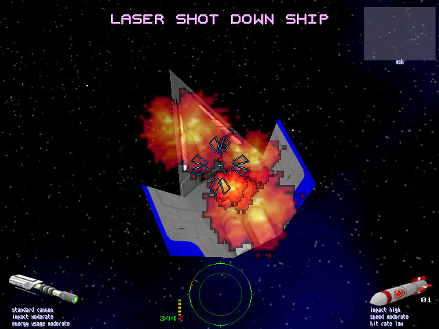
to and rotate about the objects center. Particles are also used to visualize
the points of impact of lightning beams onto a protective shield. At the
points of impact small particle spheres are created, their particles moving
quickly about the spheres surface in a random manner.
Since particles have a constant depth-value
over their entire surface, they can be rendered very quickly using the
(already filled) z-buffer to resolve visibility. Previous z-values have
to be checked only against this constant depth-value, i.e., no depth-values
need be interpolated. Because of the simplicity of this approach, it is
perfectly feasible for software-rendering. Note that this is only true
since polygons do not need to check the z-buffer, as detailed in the preceding
section.
 Figure 4: Spacecraft with lightning device activated,
energy fields in the background
Figure 4: Spacecraft with lightning device activated,
energy fields in the background
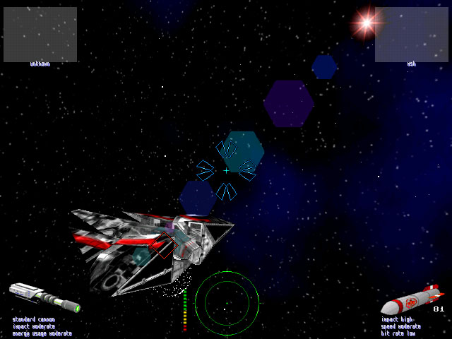
3.4 Additional special effects
Last, there is the possibility to render additional special
effects using whatever technique is appropriate. Some things we do in Parsec
after everything else has already been rendered are, for example, a simple
lens-flare effect and fading the entire screen to a certain color, say,
blue if the player is hit. We currently model lens-flare using differently
sized and colored hexagonal transparency-textures. A single ray is traced
to the light-source (a sun) and this rays points of intersection with
the lenses of an arbitrary system of lenses are used to infer positions
for these textures.
4. Implementation
Our current implementation of Parsec natively supports MS-DOS
and Win32 (Windows 95/NT with DirectX 3/5) as host platforms. The rendering
subsystem can be changed on-the-fly between pure software rendering and
hardware-accelerated rendering on boards equipped with the Voodoo Graphics
accelerator by 3Dfx Interactive, using their proprietary Glide API [Glide].
Our software renderer mostly consists of hand-optimized 80x86 assembly
language code. The perspective-correct texture-mapper supports subpixel
and subtexel precision and linearly interpolates texture coordinates for
16-pixel subspans. That is, the necessary homogeneous division is performed
only every 16 pixels. This approximation to the true perspective hyperbola
has proved to be sufficient in order to be indistinguishable from full
evaluation at every pixel. The software renderer supports resolutions ranging
from 320x200 up to 1280x1024, 800x600 being smooth enough for satisfying
gameplay on mid-range desktop PCs. We also support different color-depths:
8-bit color in palettized mode, hicolor using 16 bits per pixel, and true-color
with 24 bits per pixel, although true-color has been incorporated for experimental
reasons only. Limited transparency (alpha-blending) is supported even in
palettized modes. With hardware-rendering we currently support 640x480
resolution and a color-depth of 16 bits per pixel. Alpha-blending is essential
to displaying the command-console which can be overlaid upon the screen
at any time, in order to view and alter various engine parameters.
In order to achieve high platform
portability, the entire code-base is structured in subsystems, only the
system-dependent of which need to be implemented anew for each new platform,
as well as making the aforementioned on-the-fly switching between software
and hardware rendering-subsystems possible. The current code-base is comprised
of about 15,000 lines 80x86 assembly language code (most of which is the
software-renderer) and about 50,000 lines of code written in a C-like subset
of C++. Since Parsec is a multiplayer-only game, we support the IPX protocol
for network gameplay on local area networks.
5. Conclusions and Future work
We have reviewed how Parsec, the three-dimensional multiplayer
space-game we are currently developing, renders each frame using multiple
layers. This is especially important for achieving convincing realism and
still being able to maintain high frame update rates. We have described
rendering of layers in exactly the same order as each frame is composited
from back to front. We have emphasized the ideas employed to render a panoramic
outer-space background. Furthermore, we have looked at how various special
effects are rendered, mostly using the integrated particle system.
In the future we would like to supersede
the IPX network code by TCP/IP and internet-gameplay. For this we are going
to develop a network-server where players will be able to log in and join
games hosted by others already playing. We would like to make the network-architecture
scaleable via dead-reckoning and other techniques used in virtual environments.
We would also like to incorporate more colorful particle effects and additional
special effects, since 16bpp rendering is not performance-constrained anymore,
due to contemporary hardware accelerators. Host-platform support is also
likely to increase. We are also working on the integration of smooth (progressive)
levels of detail technology to make rendering huge carriers possible in
the future. Last but not least, we are currently working on many new objects
exploiting 16bpp colors and higher polygon counts, since our old spacecraft
have been designed for a single 8-bit palette.
Future improvements and other news
will be announced on the Parsec Homepage [Parsec]. As soon as we are ready
to release them, we will also make self-running demos and fully playable
versions for all supported host platforms freely available for download
on this web-page.
6. Acknowledgments
I would like to thank Clemens Beer and Andreas Varga for
their help with creating the panoramic background images and their ongoing
work on the Parsec project. Stefan Poiss composed the music and created
the sound-effects. Alex Mastny designed the space-ship that can be seen
in the screen-shots. Alexander Fuchs rendered particle textures and background
planets. Zsolt Szalavari helped me with preparing the paper and talk.
7. References
-
[Berm94] Deborah F. Berman, Jason T. Bartell,
and David H. Salesin. Multiresolution Painting and Compositing. In SIGGRAPH
94 Conference Proceedings. pp. 85-90, 1994
-
[Blin76] James F. Blinn and
Martin E. Newell. Texture and Reflection in Computer Generated Images.
In Communications of the ACM, 19(10). pp. 542-547, 1976.
-
[Chen93] Shenchang Eric Chen and
Lance Williams. View Interpolation for Image Synthesis. In SIGGRAPH 93
Conference Proceedings. pp. 279-288, 1993.
-
[Chen95] Shenchang Eric Chen. QuickTime
VR -- An Image-Based Approach to Virtual Environment Navigation. In SIGGRAPH
95 Conf. Proceedings. pp. 29-38, 1995.
-
[Glide] 3Dfx Interactive.
Glide Rasterization Library. See http://www.3dfx.com.
-
[Gree86] Ned Greene. Environment
Mapping and Other Applications of World Projections. In IEEE Computer Graphics
and Applications, 6(11). pp. 231-238, 1986.
-
[Hilt94] Travis L. Hilton and
Parris K. Egbert. Vector Fields: an Interactive Tool for Animation, Modeling
and Simulation with Physically Based 3D Particle Systems and Soft Objects.
In Proceedings of Eurographics 94 Conference. pp. C329-C338, 1994.
-
[Leng97] Jed Lengyel and John
Snyder. Rendering With Coherent Layers. In SIGGRAPH 97 Conference Proceedings.
pp. 233-242, 1997.
-
[McMi95] Leonard McMillan and Gary Bishop. Plenoptic
Modeling: An Image-Based Rendering System. In SIGGRAPH 95 Conference Proceedings.
pp. 39-46, 1995.
-
[Parsec] Parsec A 3-D Network
Space Fight Simulator. More information available from http://www.cg.tuwien.ac.at/~msh/parsec.html.
-
[Reev83] William T. Reeves. Particle Systems
- A Technique for Modeling a Class of Fuzzy Objects. In SIGGRAPH 83 Conference
Proceedings. pp. 359-376, 1983.
-
[Reed94] Todd Reed and Brian Wyvill. Visual
Simulation of Lightning. In SIGGRAPH 94 Conference Proceedings. pp. 359-363,
1994.
-
[Spen97] Greg Spencer, Peter Shirley, Kurt
Zimmermann, and Donald P. Greenberg. Physically-Based Glare Effects for
Digital Images. In SIGGRAPH 95 Conference Proceedings. pp. 325-334, 1995.
-
[Szel96] Richard Szeliski. Video
Mosaics for Virtual Environments. In IEEE Computer Graphics and Applications,
16(3). pp. 22-30, 1996.
-
[Szel97] Richard Szeliski and Heung-Yeung
Shum. Creating Full View Panoramic Image Mosaics and Environment Maps.
In SIGGRAPH 97 Conference Proceedings. pp. 251-258, 1997.
8. Screenshots
Here you can view some screenshots of the Voodoo Graphics
version of Parsec that appear only in the HTML version of this paper. Click
on the images to view them in their original 640x480 resolution.
| Parsec Screenshot
#1 |
Parsec Screenshot #2 |
Close-up view of a firebird.
An object-camera is available for every spacecraft. |
Chasing a firebird trying to escape.
A sun as light-source causes lens-flare. |
| Parsec Screenshot
#3 |
Parsec Screenshot #4 |
In-flight shot of a firebird with its
lightning-device activated. |
A firebird is destroyed by beams of lightning.
The protective shield is activated as soon as the beams hit. |
| Parsec Screenshot
#5 |
Parsec Screenshot #6 |
A humming-bird starting to explode.
Semi-transparent textures are overlaid multiple times. |
Being in the midst of a particle explosion. |
| Parsec Screenshot
#7 |
Parsec Screenshot #8 |
Scavenger surrounded by invulnerability
shield
rendered using a particle-sphere. Planet in the background. |
Flying right through an energy field. |
![[CESCG logo]](../../CESCG/images/cescg98.small.gif)
![[CESCG logo]](../../CESCG/images/cescg.small.gif)